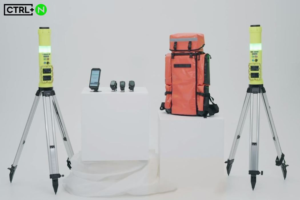
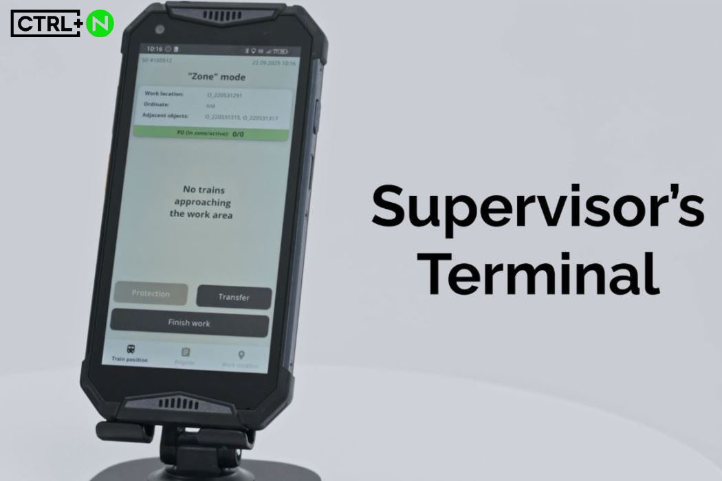
The company's team of professionals has developed a safety and warning system for railway workers. Everyone knows that railways are a high-risk environment. Workers are exposed to high/low temperatures, excessive noise, vibrations, electromagnetic influences, poor visibility, and poor audibility of train approaches to their work areas. This is a unique system designed to ensure the safety of railway workers. It provides advance warning of approaching trains. The smartwatch transmits a signal using a vibration motor, a buzzer inside, and a display, while the SPAD uses a loud siren and an optical signal.
My personal achievements in developing and testing this system:
1. SPAD:
- implemented the nRF21540 chip in the device's circuit, which increased the BLE Mesh range from 50 meters to 150 meters (a 3x increase in communication range);
- organized testing and debugging of UWB, which allowed to increase the stability and range of the system by 25%;
- performed impedance matching of the PCB BLE antenna using VNA (by trimming the PCB antenna), which increased the signal power and transmission range by another 50%;
- optimized the device's power consumption and heating, which increased the maximum operating time by 30%;
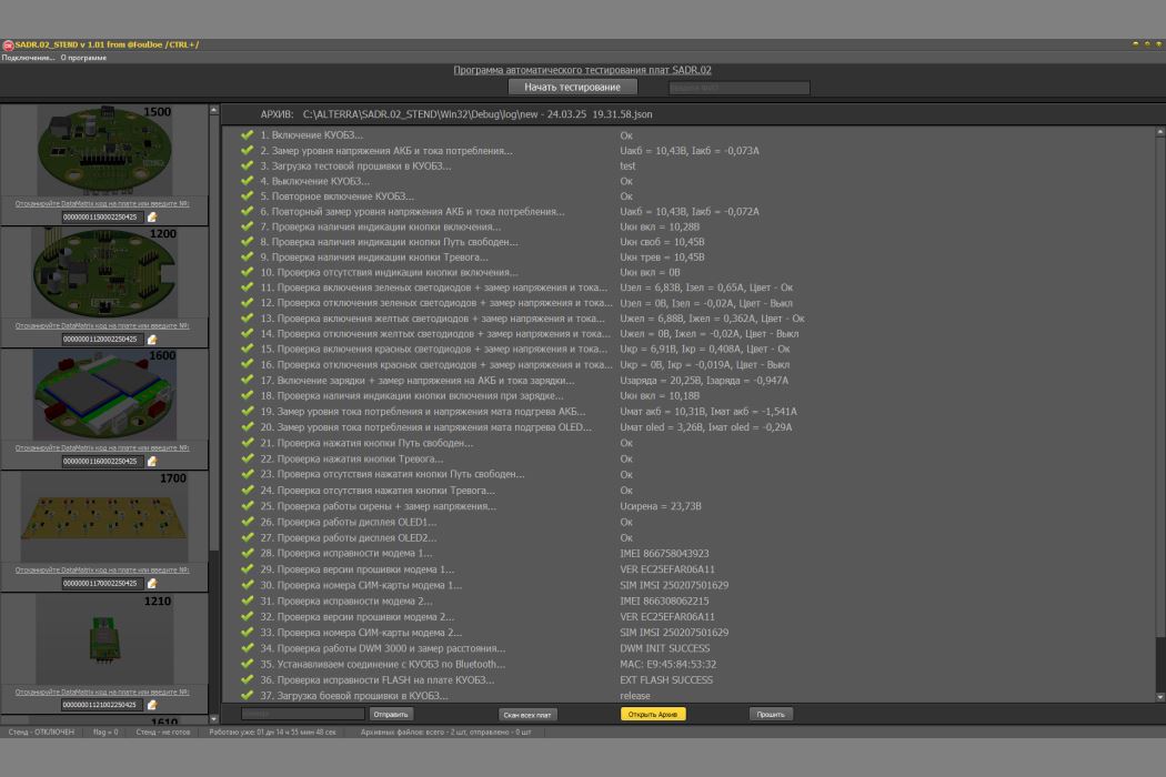
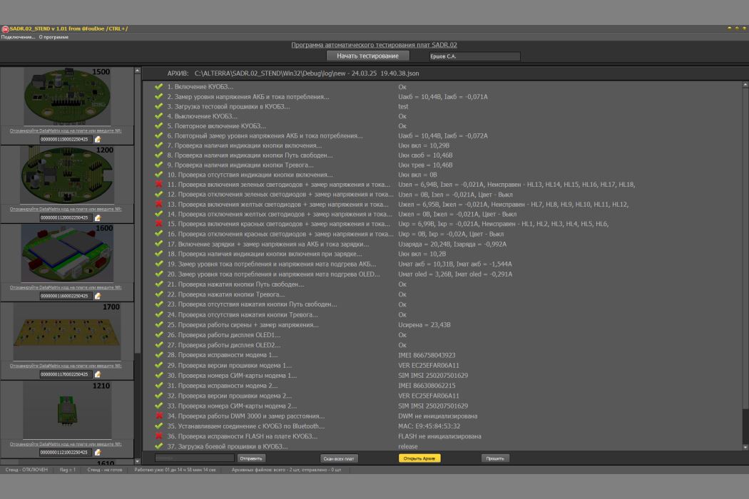
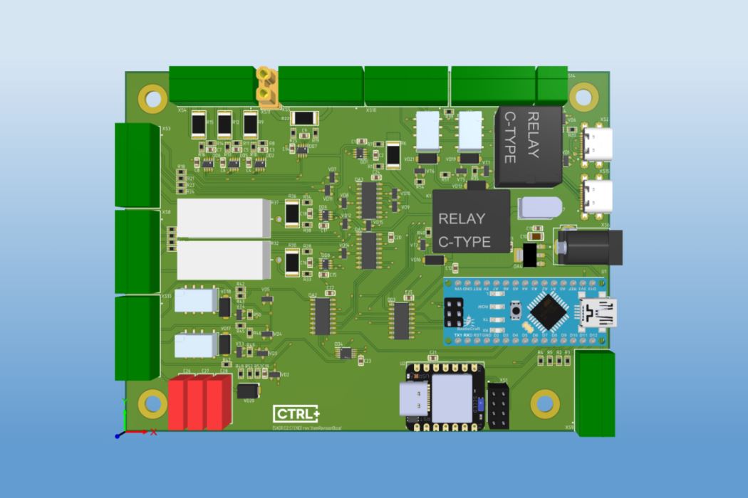
- created an automated test stand for product boards;
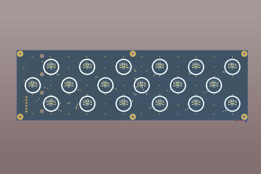
- designed an LED test board in Altium;
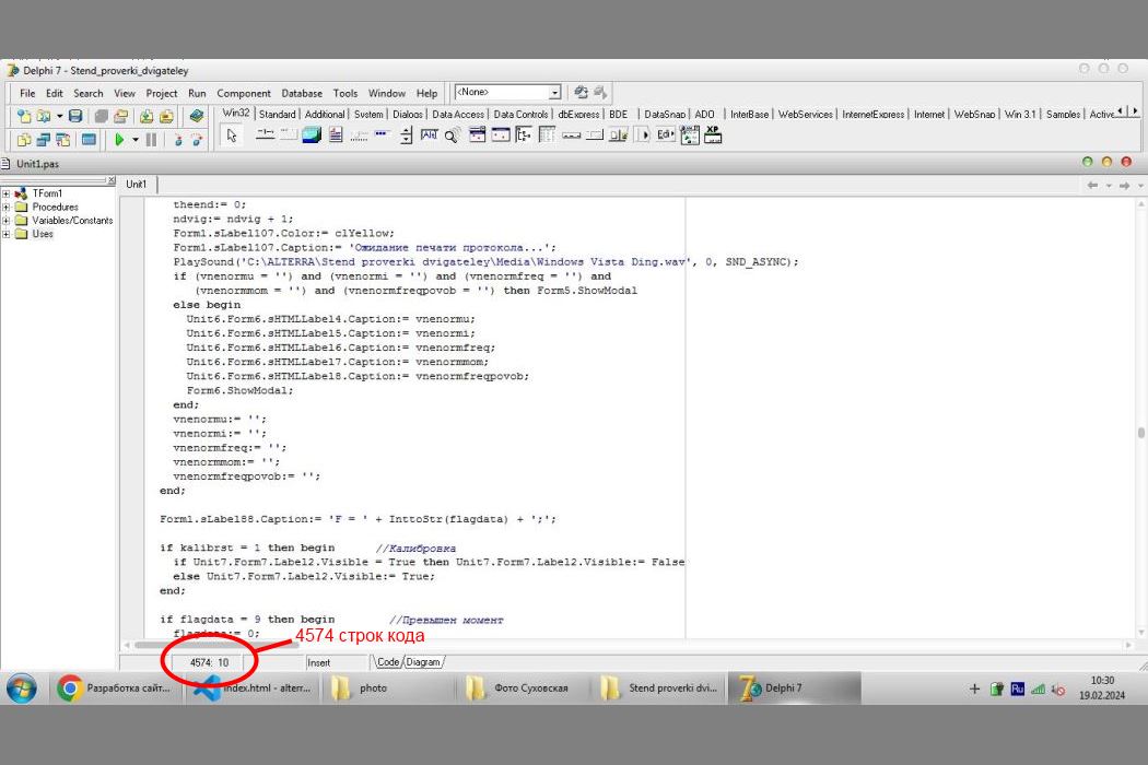
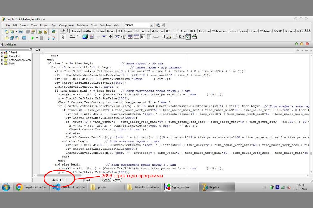
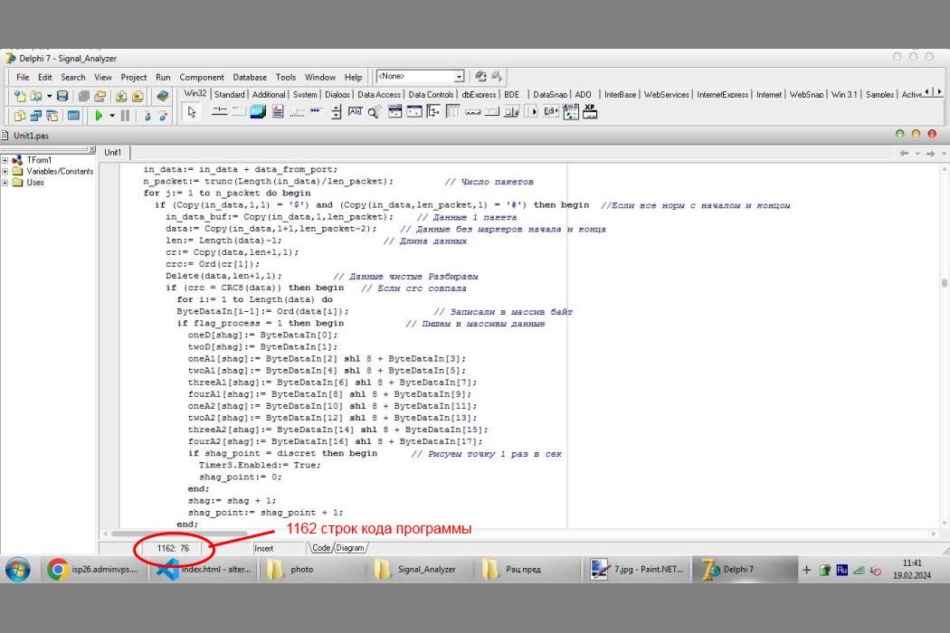
- wrote software for the Delphi PC stand (PC user part);
- developed an understandable instruction for assembling the device in a 3D modeling program in the form of exploded diagrams;
- conducting climatic, energy, and other tests on the sample;
- identified poor performance of the GPS receiver, analyzed the circuit, found flaws, made improvements, and maximized performance;
- organized manual, automated, and load testing, which allowed us to identify many bugs and improve the user experience.
2. Smart Watch:
- developed the testing program and methodology;
- a full test of all smartwatch parameters;
- suggested improvements to refine the case;
- testing of GPS antennas (more than 10 options);
- learned how to use a VNA to measure high-frequency paths;
- performed impedance matching of the PCB BLE antenna and the ceramic GPS antenna using a VNA and a Pi matching network, which increased the signal power and transmission range by 50%;
- participation in the creation of a program and testing methodology for production.
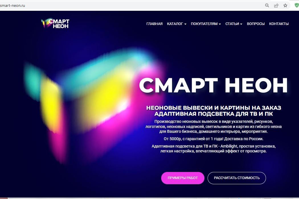
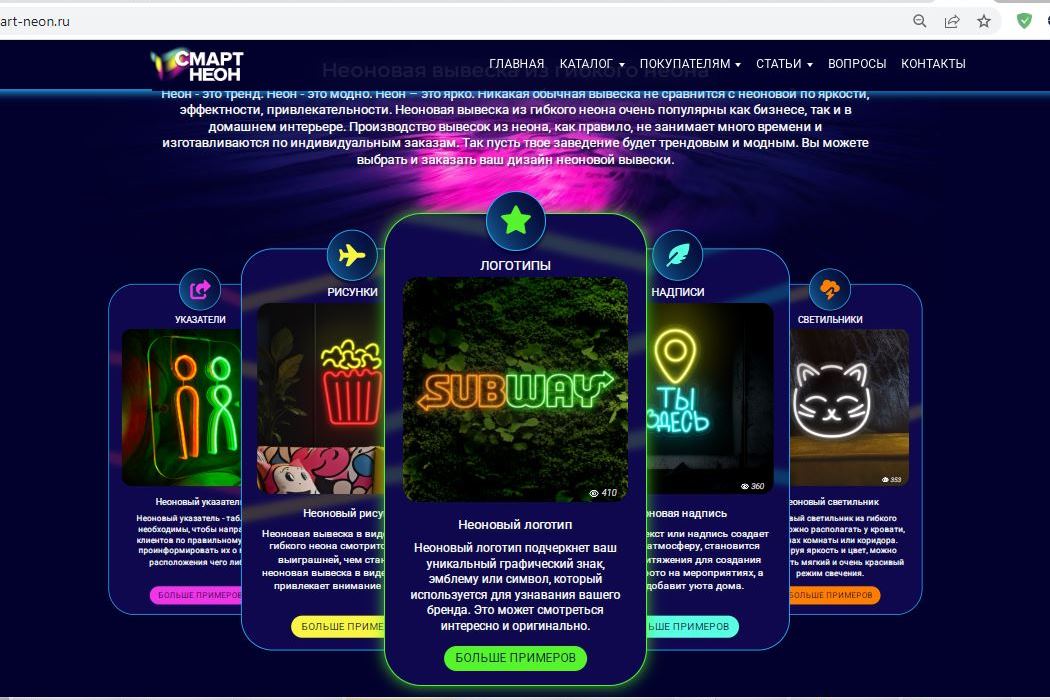
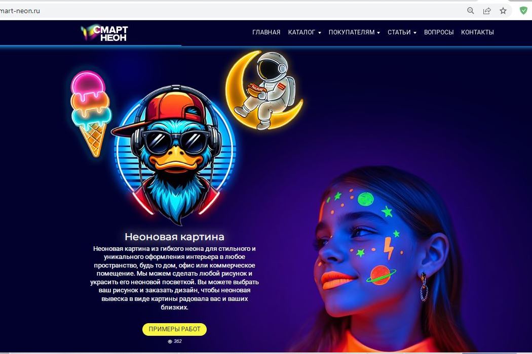
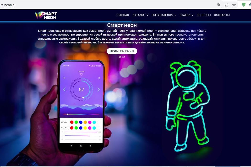
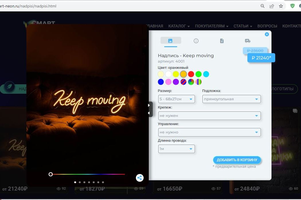
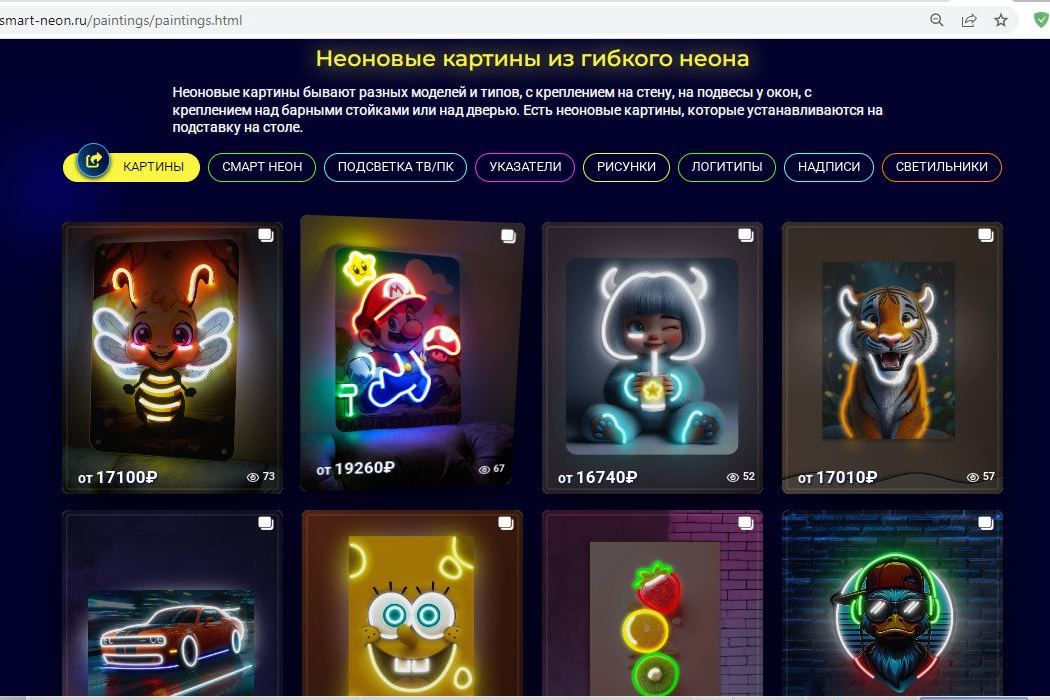
One of my best projects is a website for a company that makes custom neon signs. It uses HTML, CSS, Less, Java Script, and PHP. The website is fully responsive for PCs and all mobile devices. It has a full-fledged shopping cart with a pre-price calculator, as well as the ability to send requests and emails to the owner. The product cards have automatic view statistics, and customers can change the color of the neon sign using a slider.
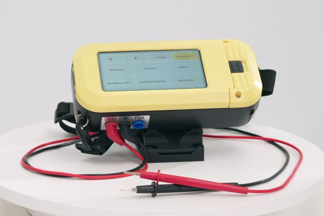
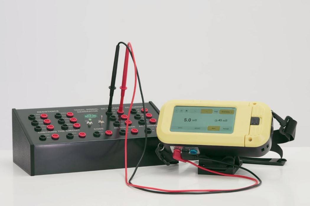
The company's professional team has developed a universal measuring module for railways. This is a unique high-precision measuring device that combines the functions of up to 10 different types of conventional measuring devices, making it very convenient and versatile. It can measure all the necessary parameters using measuring probes, as well as an inductive sensor (without probes), and is extremely useful in the field of automation and telemechanics. I have put all my heart and knowledge into this device, which I gained from my previous work on the railway.
My personal achievements in developing and testing this device:
- proposed and modified the input signal amplification circuit and implemented an EMC shield to eliminate interference and achieve a 1% accuracy in measuring a 5 mV voltage;
- optimized the internal switching of modules, which increased the device's functionality by 20%;
- implemented a digital filter circuit and an automatic Q-factor adjustment circuit using digital SPI variable resistances, which made it possible to measure the signal at different frequencies;
- implemented a digital reference signal generation scheme, which eliminated voltage fluctuations;
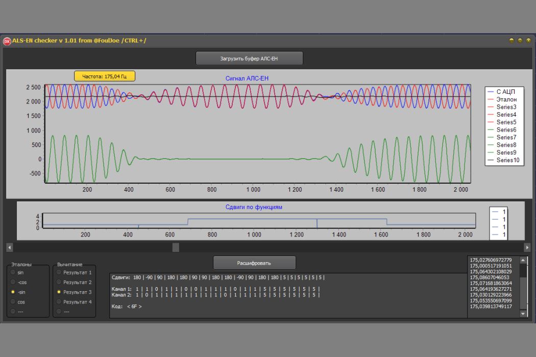
- developed on a PC (wrote in Delphi) an algorithm for DSP and decoding the input phase-manipulated signal code using the Bauer code, which was completely implemented to replace the poorly functioning one;
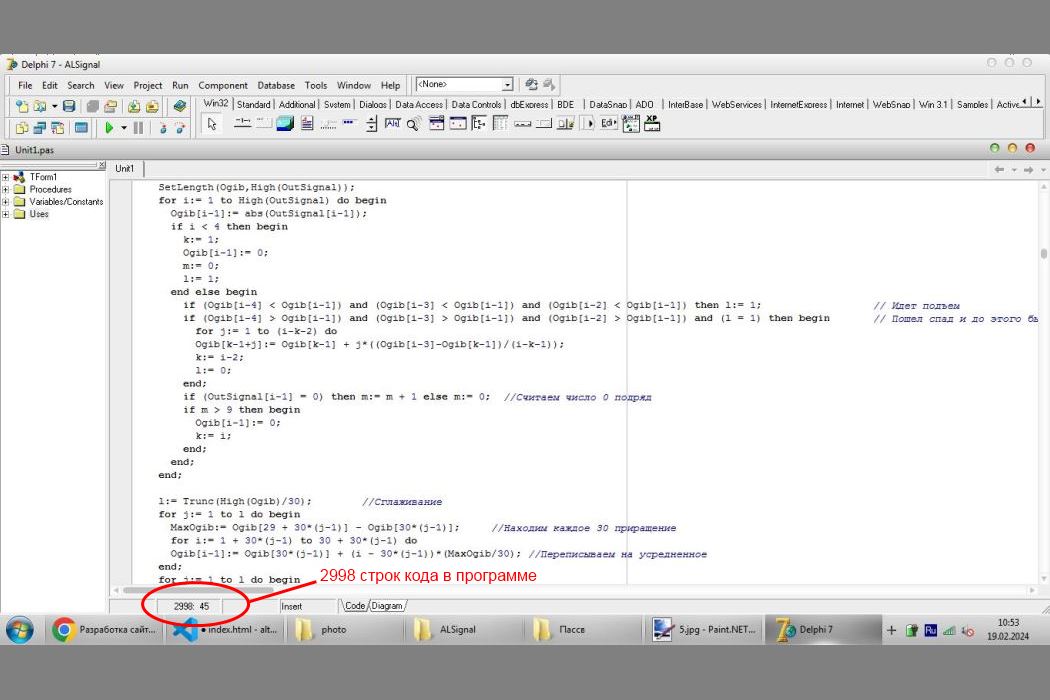
- developed an AM signal decryption algorithm on a PC (written in Delphi), which was implemented instead of a poorly working one;
- developed a PC-based (written in Delphi) DSP algorithm that includes FFT and voltage measurement at all frequencies, which was implemented as a super feature of the device;
- developed a unique specialized stand for generating signals similar to those on a real railway for checking and testing the device;
- Added several additional features that improve the human experience.
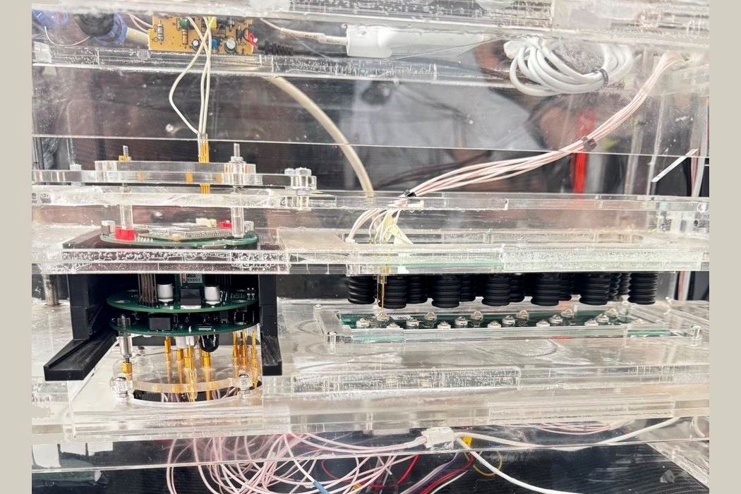
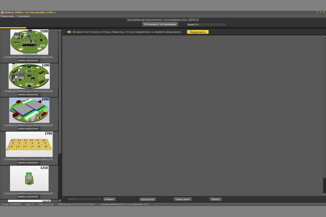
A stand for automated diagnostics of device boards has been developed. The boards are automatically tested, and all necessary voltage, current, short-circuit, line integrity, component health, and other parameters are measured.
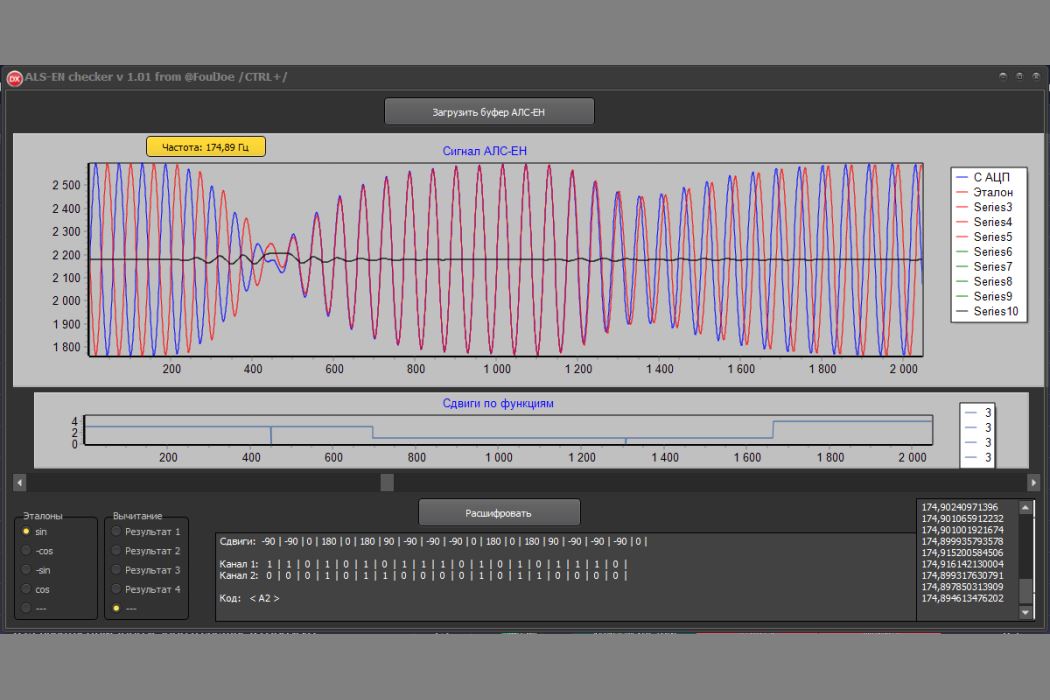
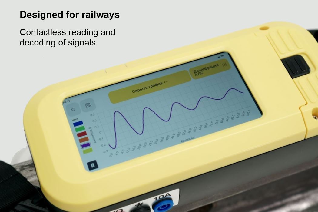
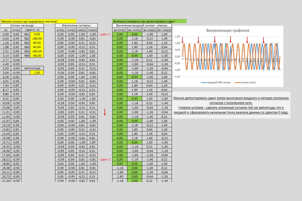
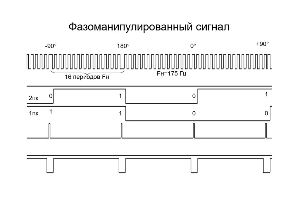
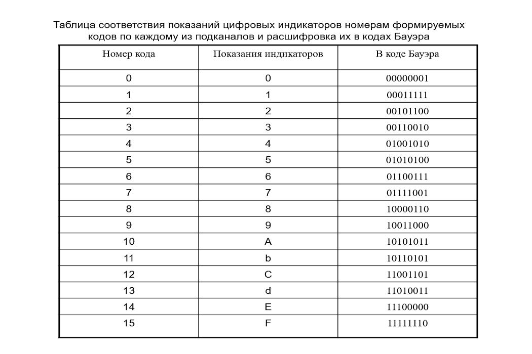
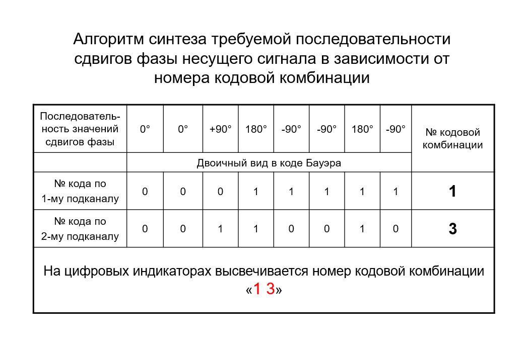
A program for decoding the ALS-EN code has been developed. The algorithm involves analyzing a phase-shifted signal with a frequency of 175 Hz. Every 16 periods, the signal's phase shifts by 0, +90, -90, or +180 degrees. The algorithm generates four reference signals: sin, -sin, cos, and -cos. By subtracting each of the reference signals from the input signal, the algorithm identifies near-zero values. Thus, it is calculated where the shift occurred - at 0, +90, -90, or +180 degrees. Next, according to the Bauer code tables, the signal code and encrypted message are decrypted.
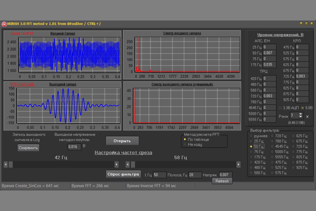
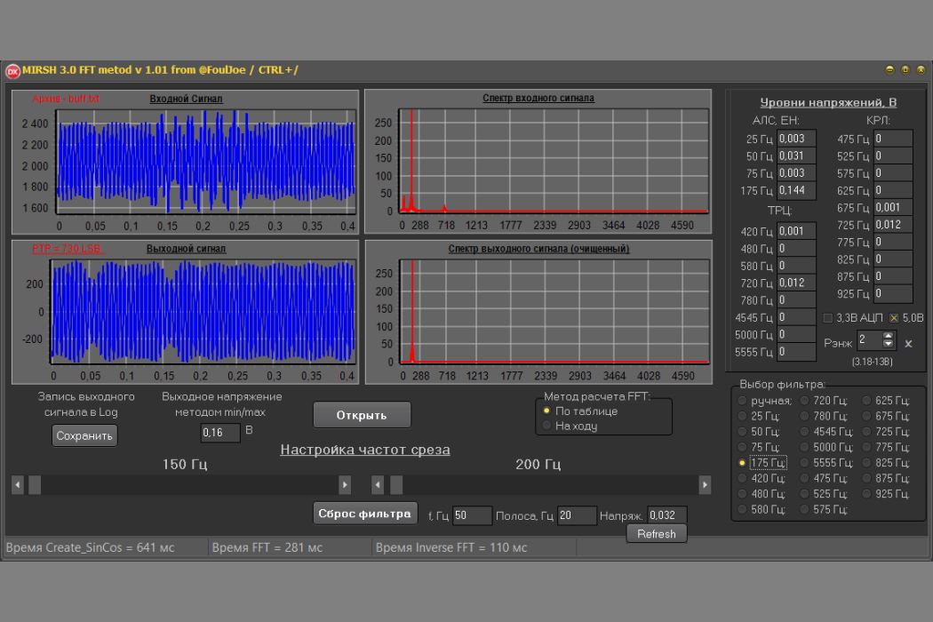
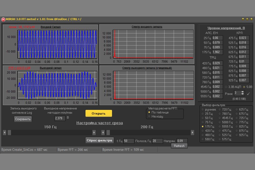
A program for calculating Fourier has been developed. The idea is to display the voltage levels of all frequencies present in the measured circuit on the measuring device's screen. The signal from the controller's ADC is analyzed using this algorithm, and the voltage level is calculated for all frequencies using the direct and inverse Fourier transform algorithm. All the information is displayed on the measuring device's screen.
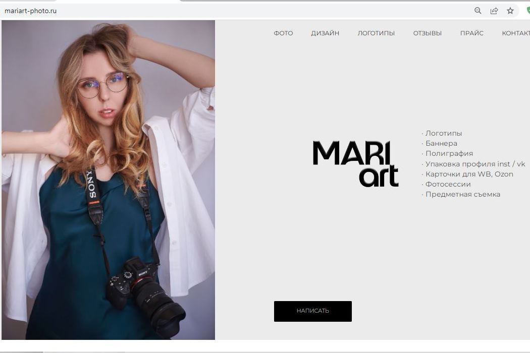
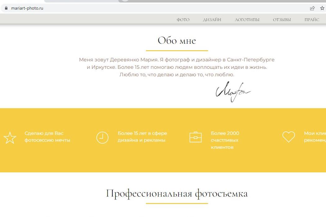
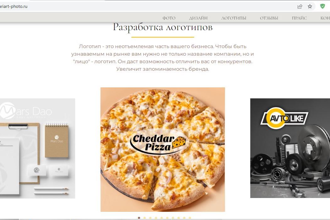
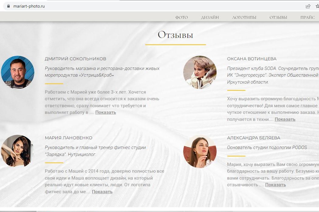
One of my first and best projects to create a website for the best photographer and designer. Used HTML, CSS, Java Script, PHP.
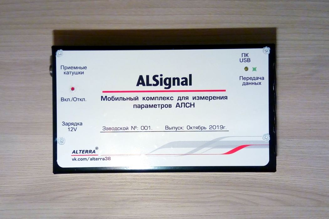
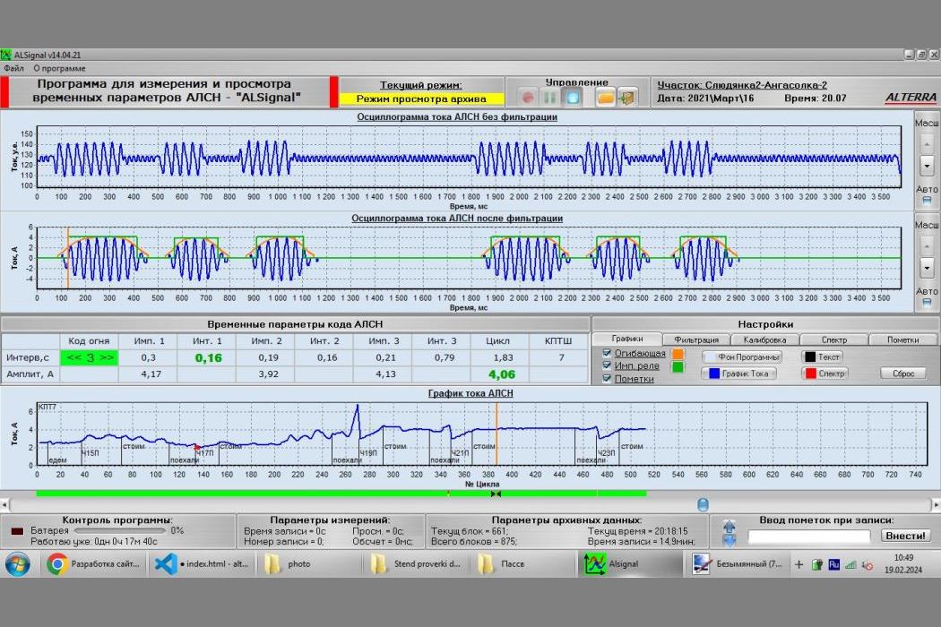
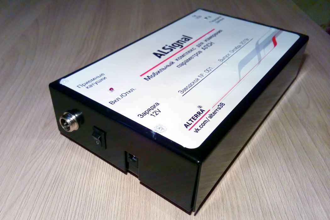
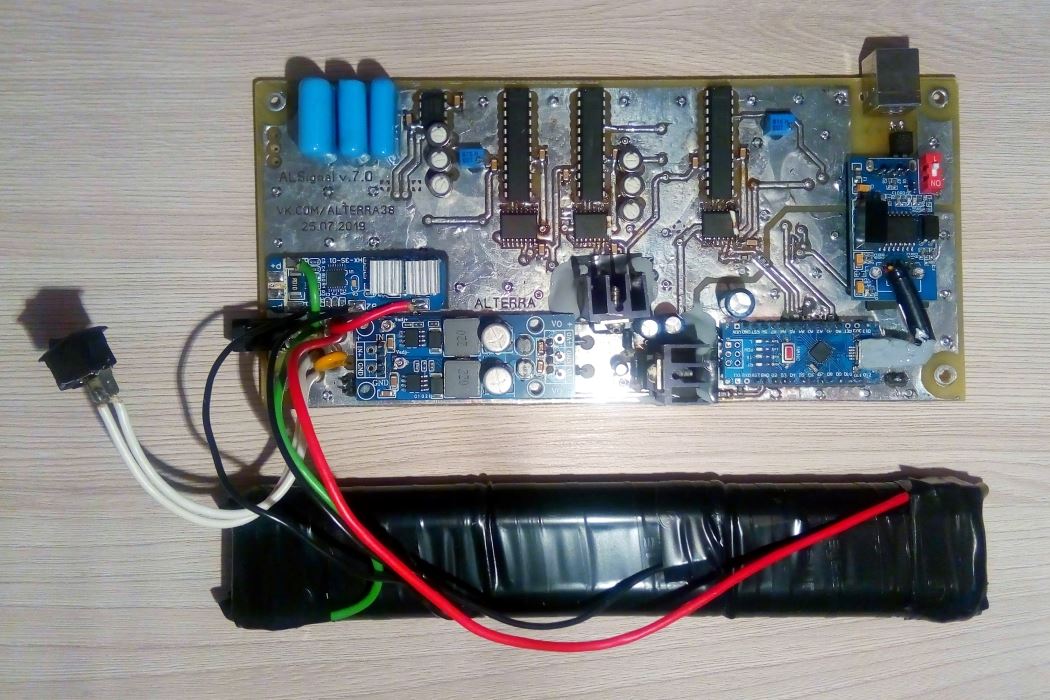
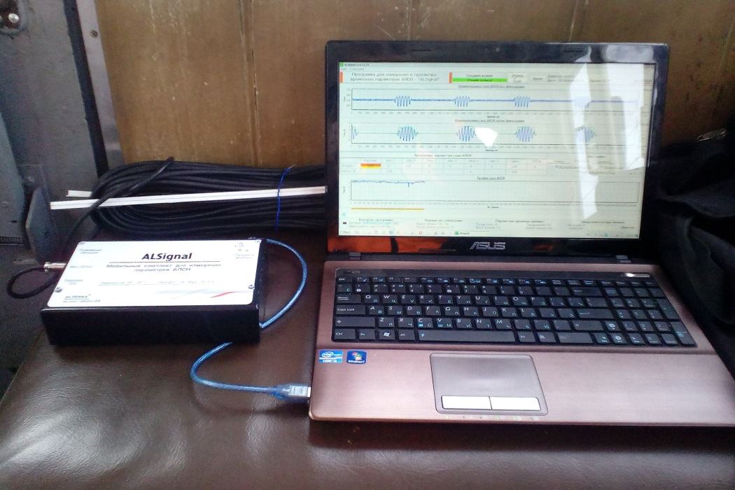
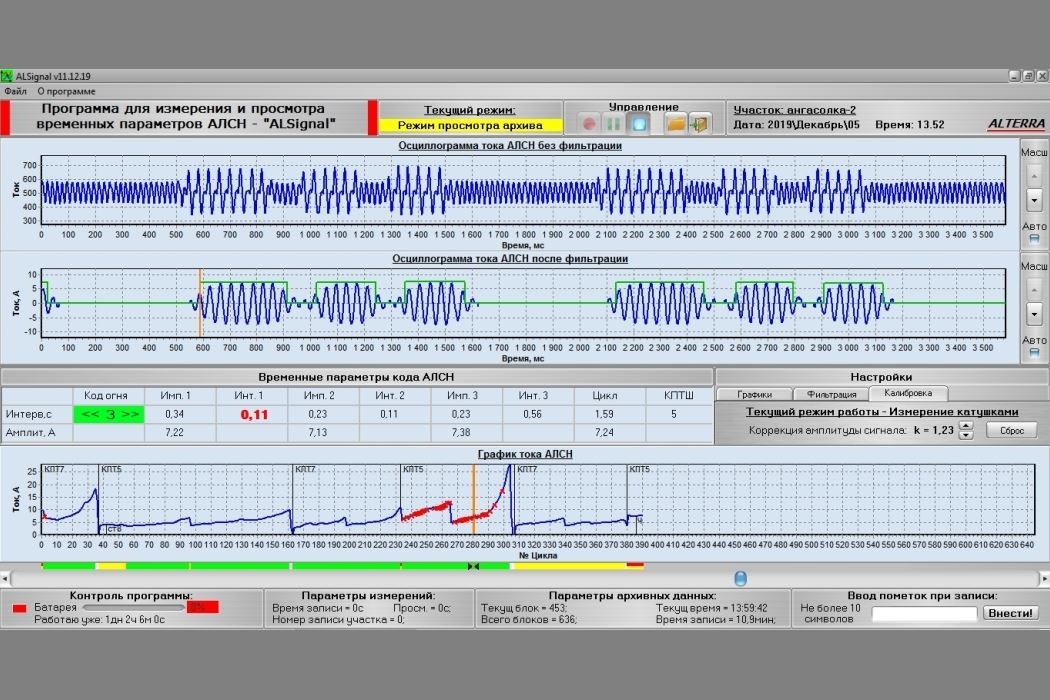
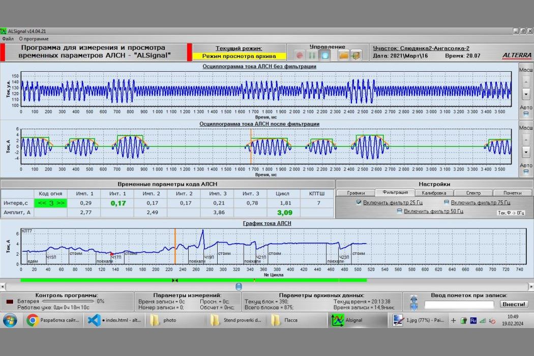
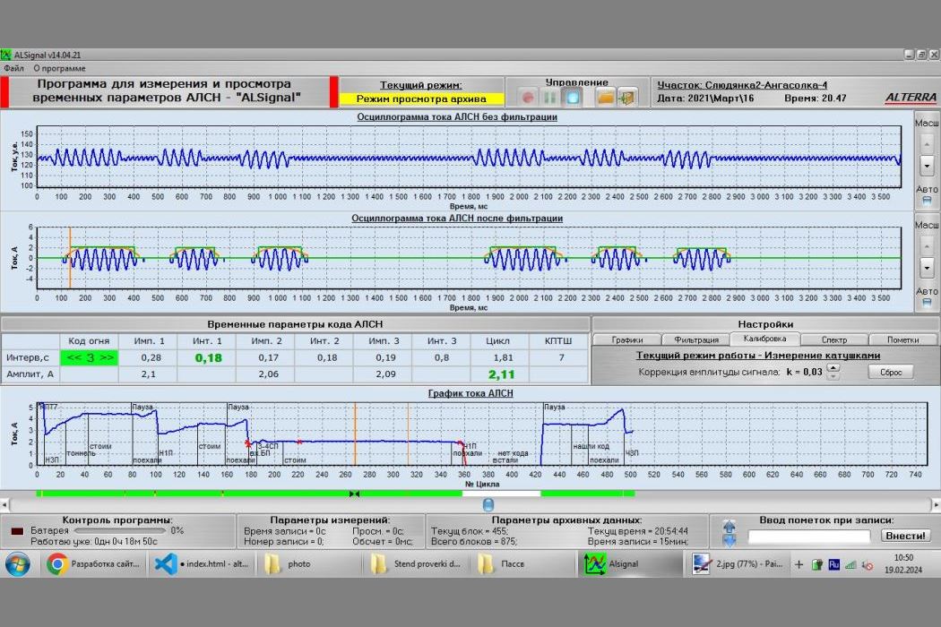
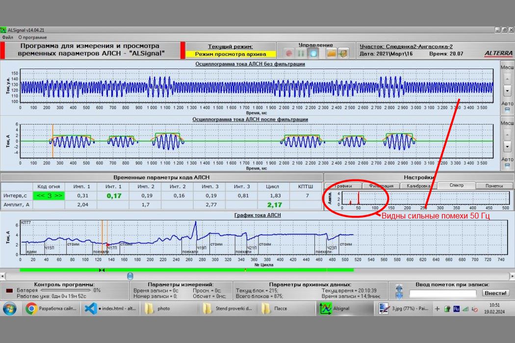
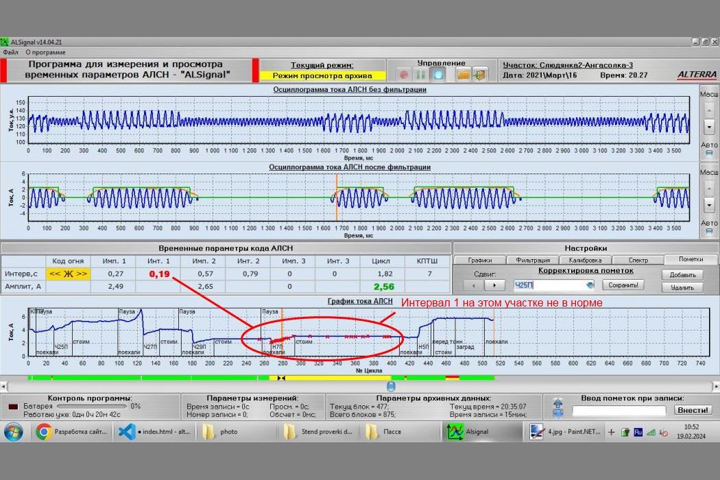
ALSignal - Mobile complex for measuring parameters of ALSN (Automatic Locomotive Signalling). Completely redesigned the main control board, changed the element base, metal housing, added new functions. This is a complex with convenient software and mobility. You can get on any train, electric locomotive, motor locomotive and measure the ALSN code on the stage or station, and not wait half a year for the laboratory car to pass. This is especially necessary when there are failures in the ALSN, and there is simply nothing to measure such things. When measuring from the locomotive cab, the graphs show the ALSN code in the form of a sinusoid and failures in areas with magnetized rails, equalization jumpers, and traction substations. They also show the asymmetry of the traction current and other parameters that cannot be measured while stationary on the track. This system is similar to the Mikar system, with the advantage of mobility, convenience, and flexibility for measurements, which is crucial for the maintenance staff of the signaling system.
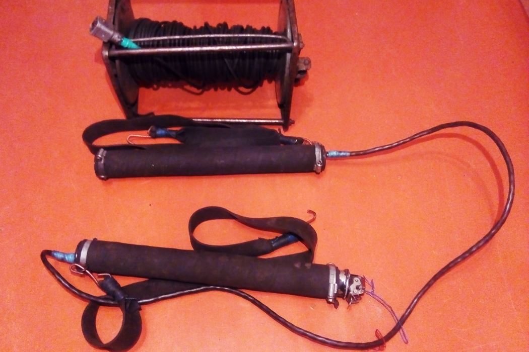
The complex consists of receiving coils, which must be fixed on the receiving coils of the locomotive, a receiver unit for primary processing and filtering of the signal, a laptop with software. The coils are connected by a shielded wire to the signal reception unit, and measurements are made in the rear cabin of the locomotive.
This is perhaps the only convenient option for visualizing the ALSN coding and equipment diagnostics processes.
The system allows you to:
1. Record the signal from the receiving coils;
2. Archive data, and after work, you can run the Archive to view the data in detail;
3. See the signal before the filter (signal in the RC);
4. See the signal after filtering (evaluate what comes to the locomotive devices - BS-DA);
5. The program calculates each pulse and interval (the time must be within a certain range). If the parameters exceed the normal range, a red cross is displayed on the current graph;
6. Based on time, recognize the type of KPTSh (KPTSh No. 5 or 7, which should be alternated constantly) and thus identify the erroneous installation of two identical KPTSh in a row;
7. The program calculates the current value of each pulse (the current must be within certain limits);
8. Based on the current value, it plots a current graph (at the bottom of the program window);
9. The program, based on the number of pulses in the code cycle, colors each cycle with the corresponding color (green, yellow, red-yellow, white), which is displayed on the locomotive traffic light in the train driver's cabin. In the image below, the program displays a colored bar, indicating that the train is catching up with the preceding train and changing its color from green to yellow. This is also useful for analysis, as when there are code errors, the program will mark the code cycle with white color, making it easier to identify the problematic area.
The device is capable of measuring the ALSN code at frequencies of 25Hz, 50Hz, and 75Hz. The program has many settings, including the ability to change the colors of the graphs and program windows, as well as to display additional graphs, such as the envelope graph (orange) or the pulse relay graph (green). The program also includes a battery charge level indicator.
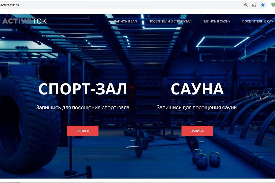
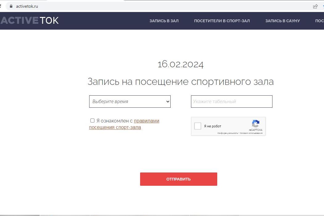
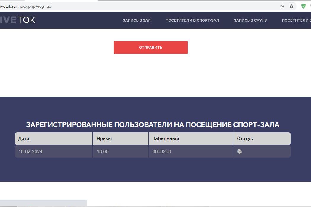
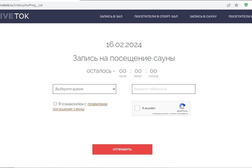
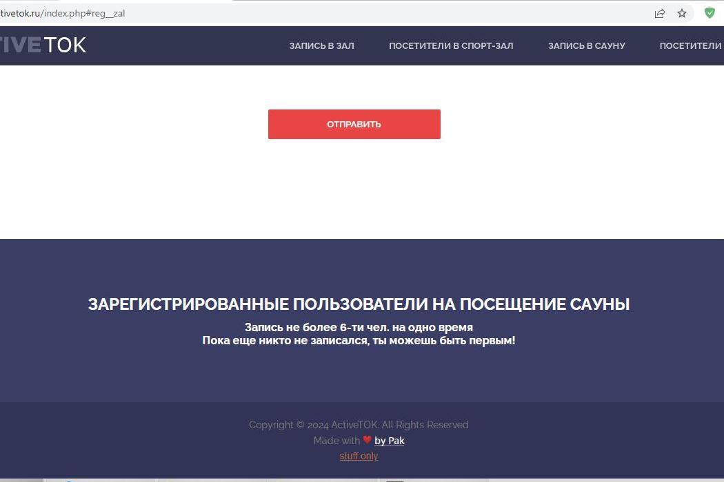
The website was developed to organize the flow of visitors to the gym and sauna. HTML, CSS, Java Script, and PHP were used. Data is recorded in the MySQL database, which allows for complete statistics on visits and the implementation of a sauna access feature based on the number of visits. The website prioritizes those who have visited the sauna the least. A progress feature is implemented, where each visit is counted and the visitor's status is updated with different emojis, encouraging them to visit the gym more frequently. A ban feature is also included for violations.
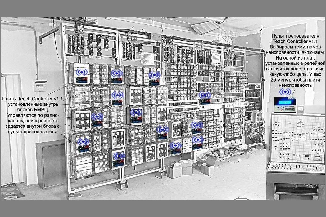
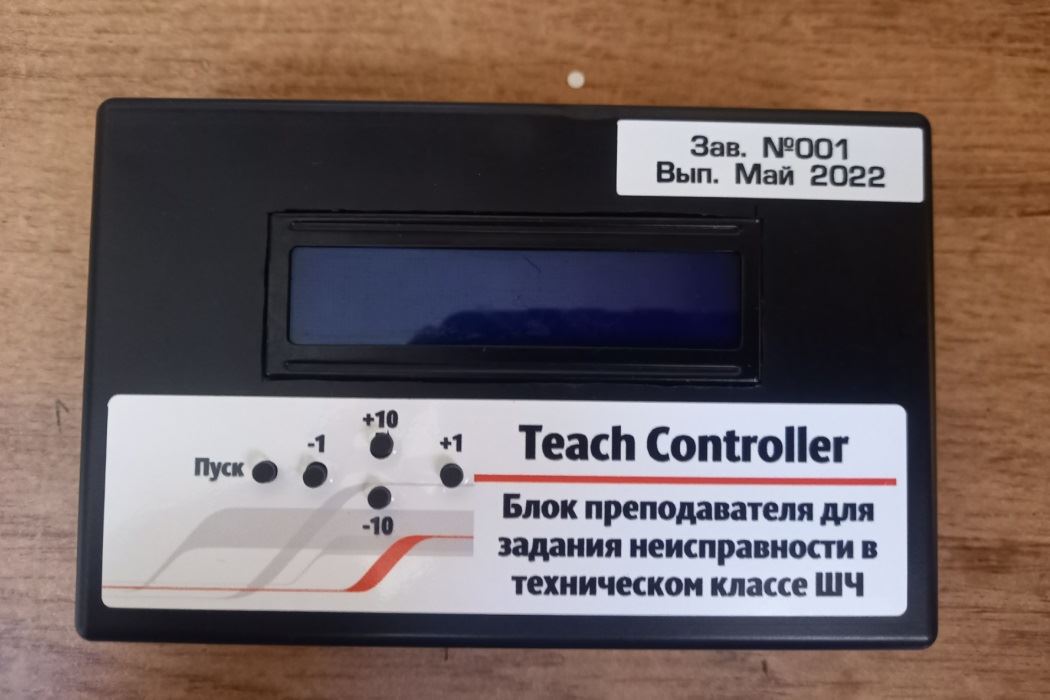
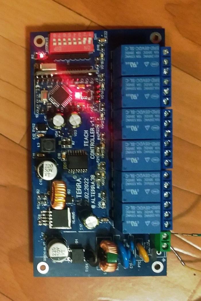
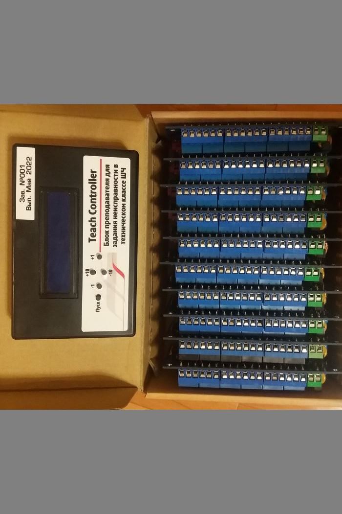
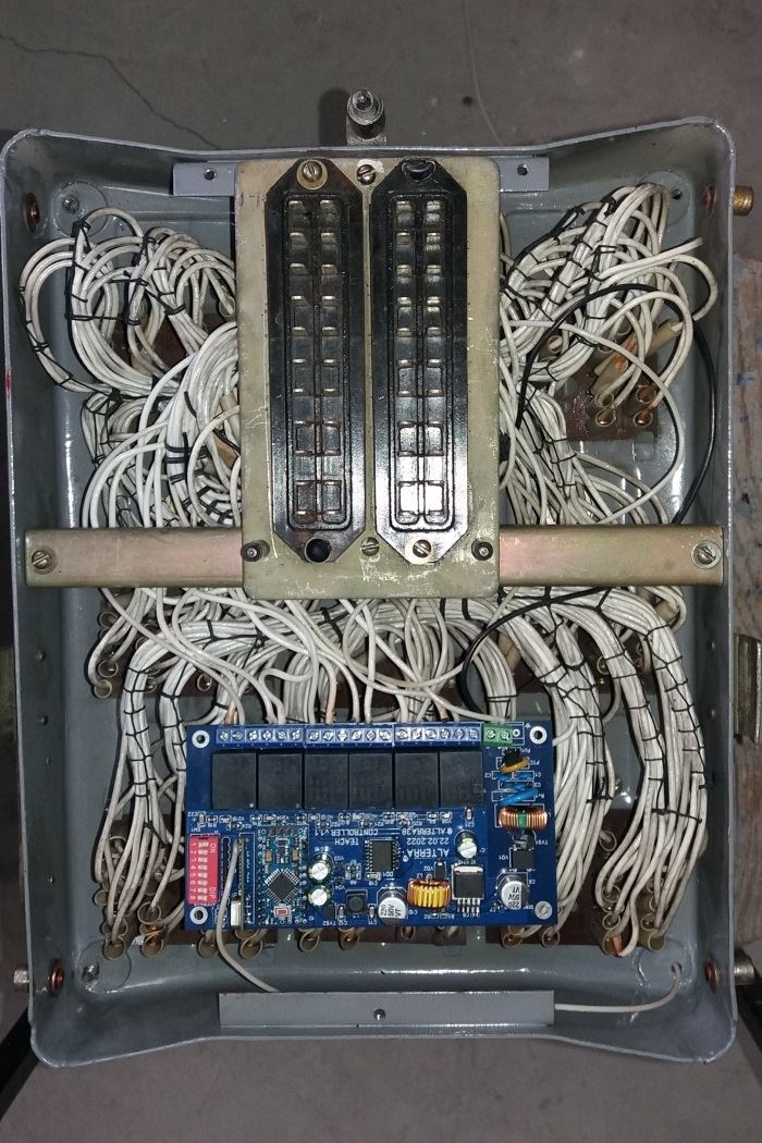
The project is a teacher's panel where malfunctions are set and receiver boards are used to receive the signal over a radio channel and turn on the required interface relay. The boards are discreetly installed inside the BMRC or relay units, and when the relay on the board is triggered, a specific circuit is interrupted. This causes a portion of the relay circuit to stop functioning.
The project's objective is to automate and "revitalize" the technical class in the School of Railway Engineering, which aims to train railway signal and block equipment electricians in troubleshooting and repairing circuitry. It is no secret that the qualifications of personnel in a railway enterprise must be at a high level, especially if it is directly related to traffic safety. Therefore, this technical class was created, as well as the Teach Controller v1.1 fault management system.
Everything happens instantly, without the training staff noticing. They have 20 minutes to figure out which part of the circuit has stopped functioning, identify the specific location, and prove it to the instructor by demonstrating measurements and explaining how the circuit works.
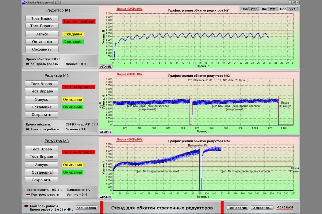
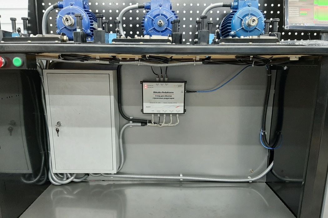
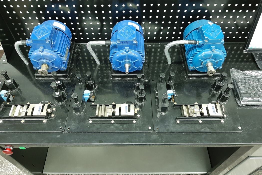
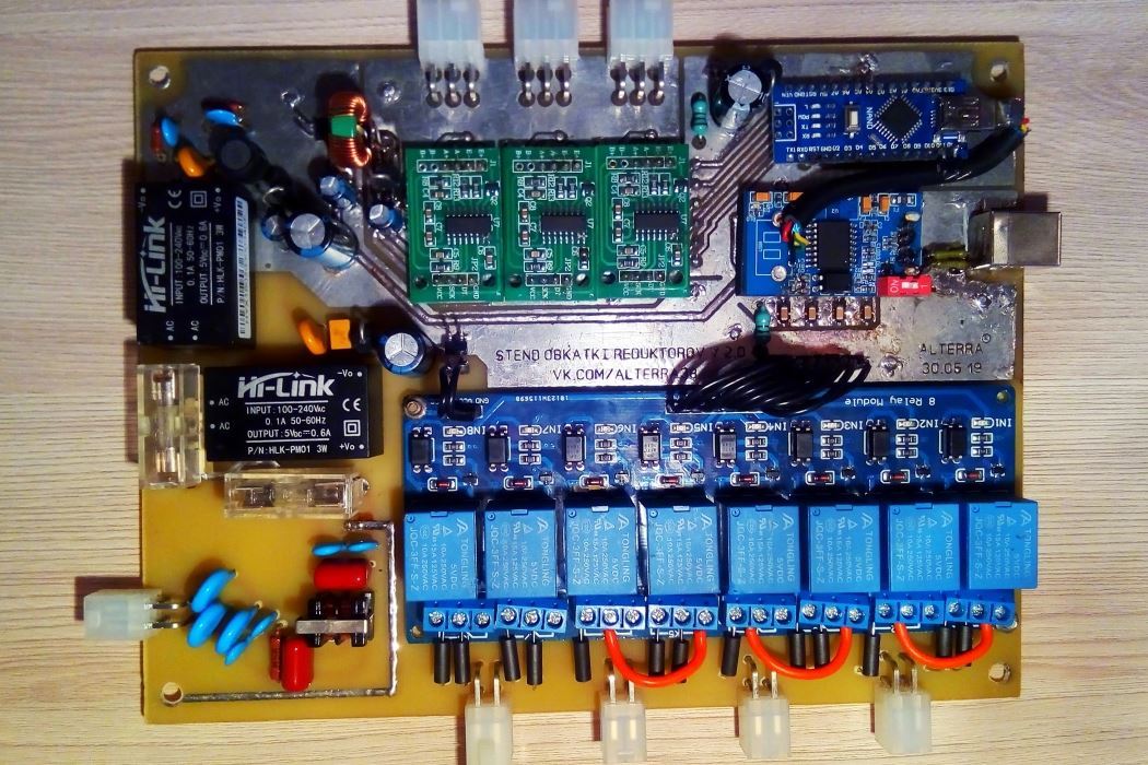
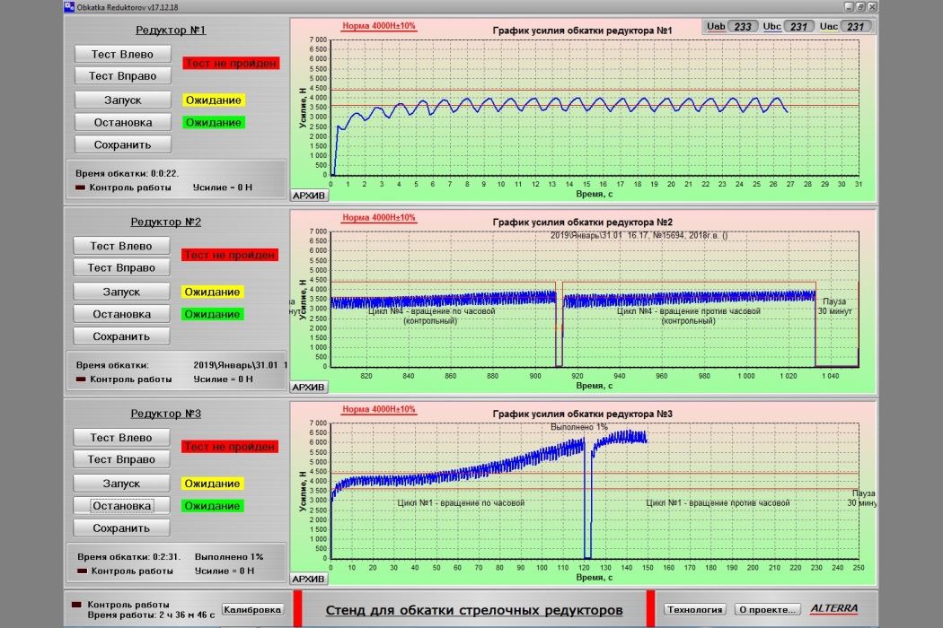
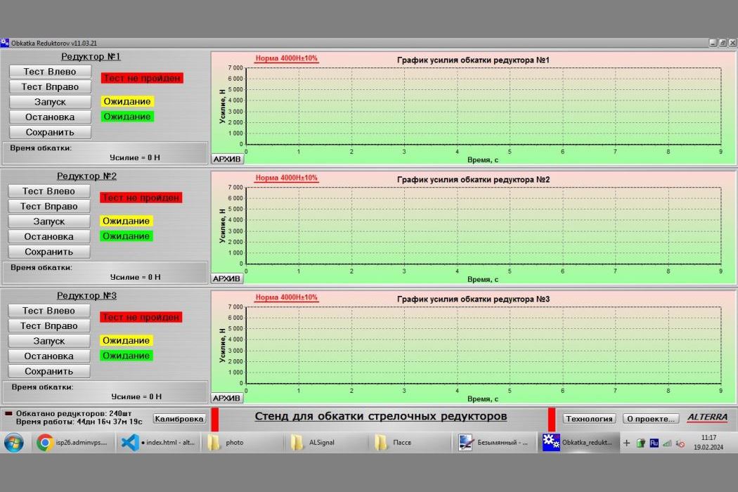
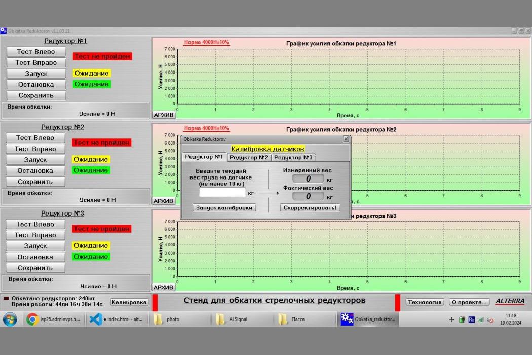
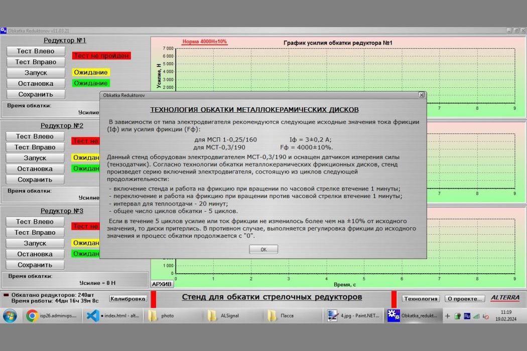
The arrow gearbox has a friction clutch, which is necessary for operation when the arrow points are abruptly stopped (if an object gets in the way). When replacing the friction discs with new ones or when overhauling them, it is necessary to grind them to ensure stable clutch operation.
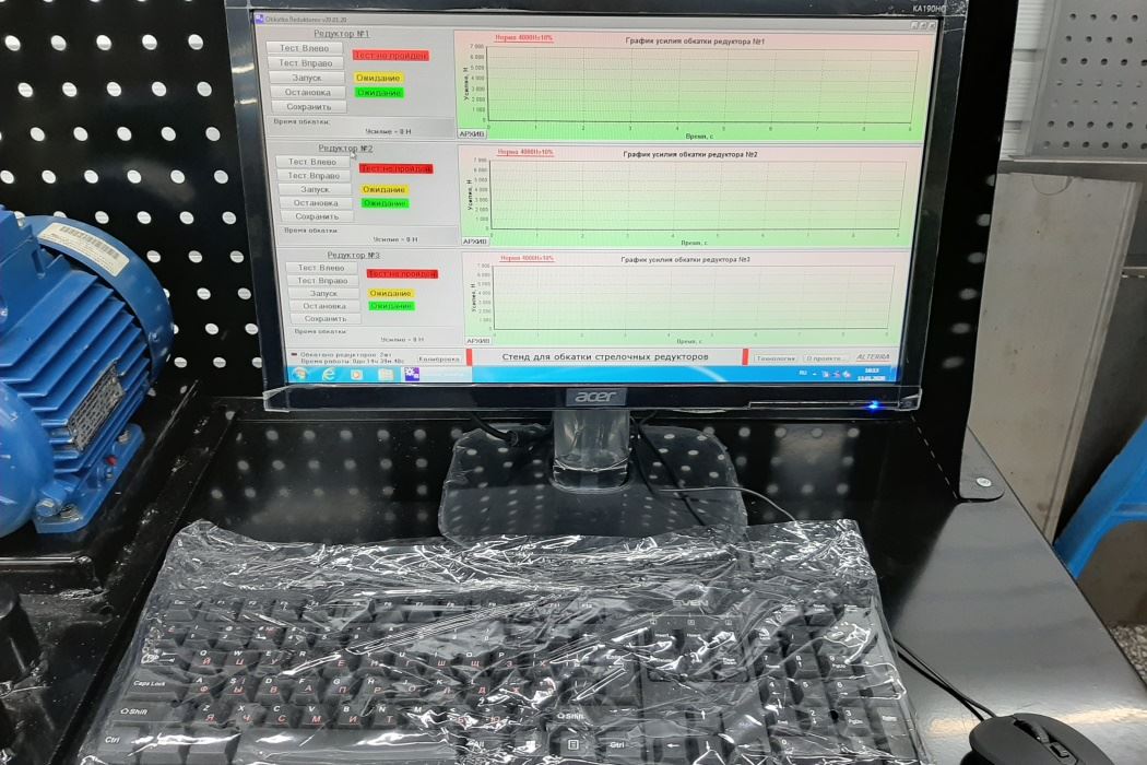
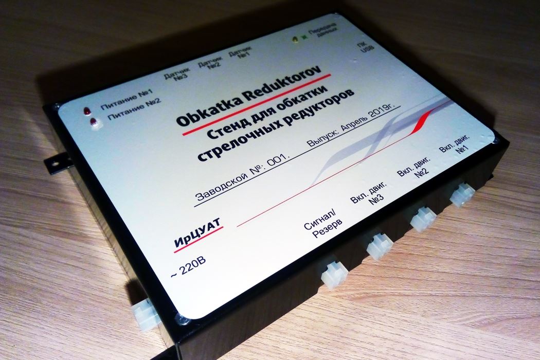
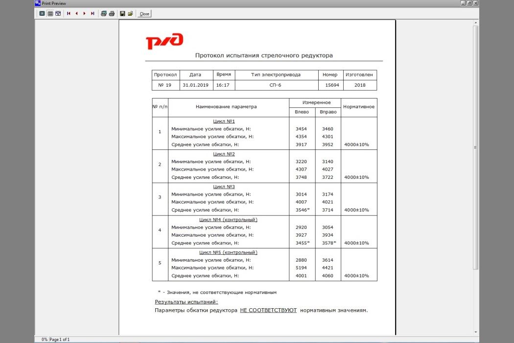
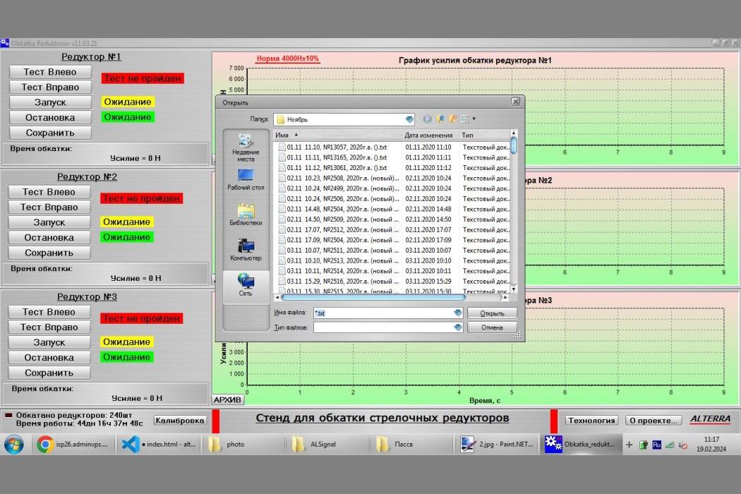
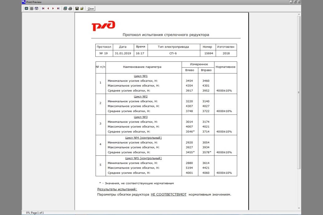
This stand was created for this purpose. The stand is fully automated and controlled by a specially designed program. The microcontroller controls the activation of the electric motors, reverses the direction of rotation, receives data on the lapping force of the friction discs in the gearbox from the load cells, and transmits and receives data from the PC. The required lapping force is set, and if the force does not change by more than 10% by the end of the lapping program, it indicates that the discs have been lapped. The program consists of 5 cycles, each cycle is the inclusion of the electric motor for 2 minutes to the right, then stop and include the electric motor to the left. Pause 30 minutes is necessary for cooling of the discs and gearbox during the run-in. All measurements are saved in the archive, which can always be viewed, as well as the run-in protocol of the gearbox is formed.
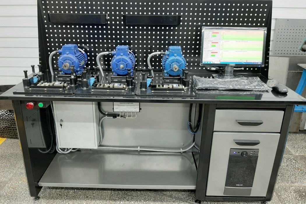
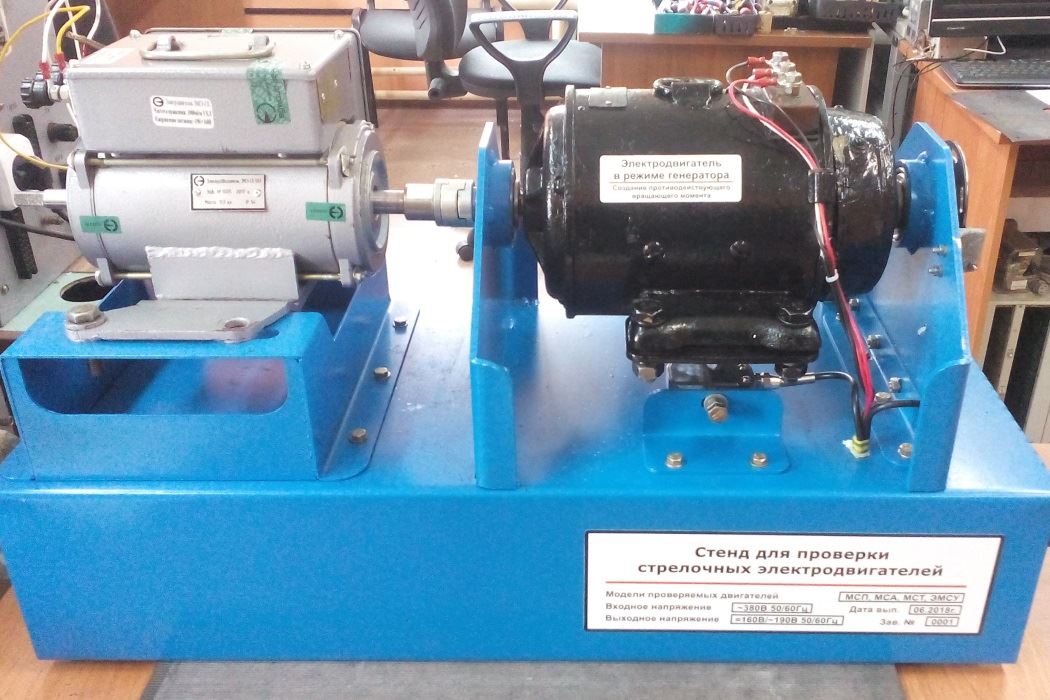
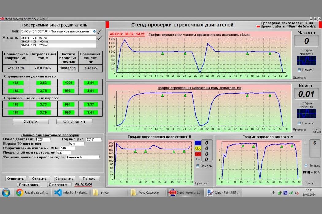
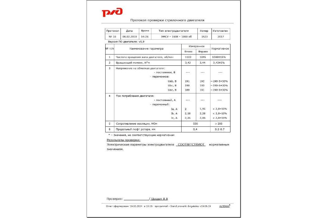
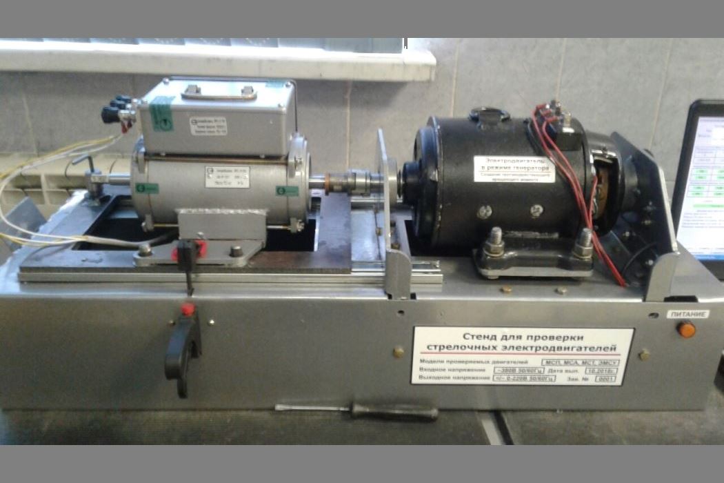
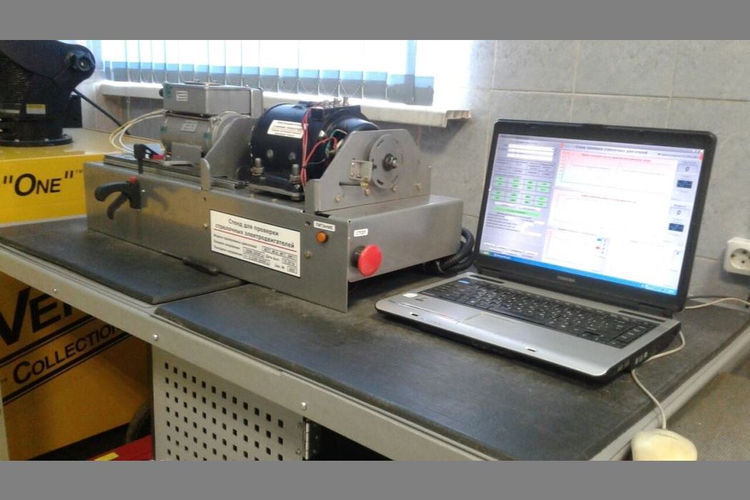
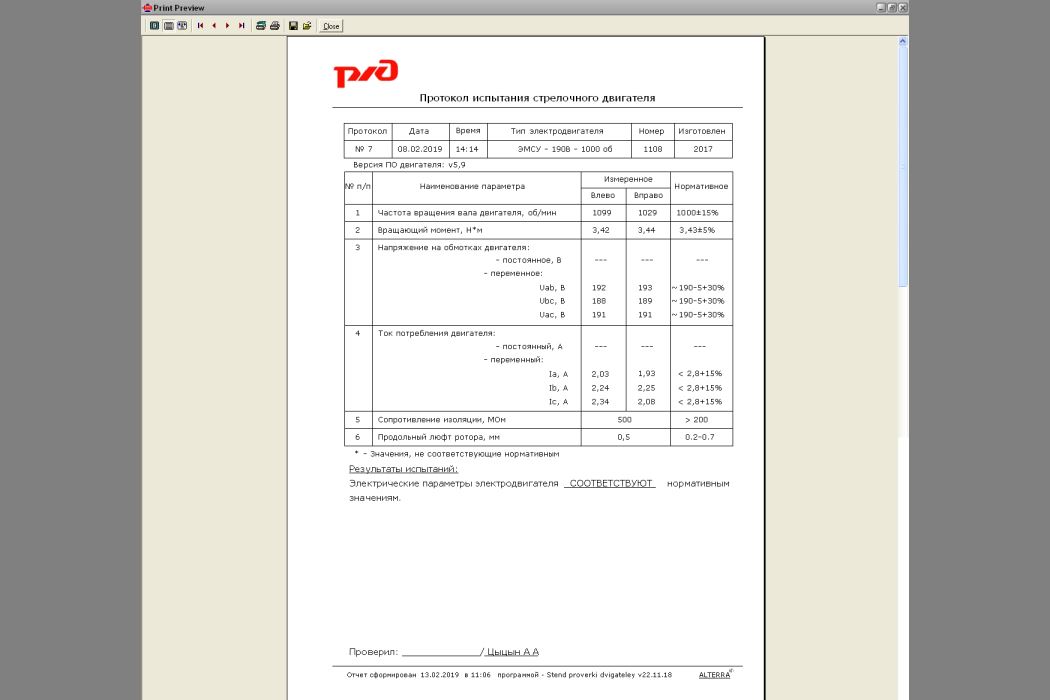
The project of the Automated Stand for testing of arrow engines of various types has been completed. In order to properly test an electric motor, it is not enough to simply turn it on and measure the voltages, currents, and shaft rotation speed. It is necessary to create a load, provide resistance to the rotation of the tested motor's shaft, and perform all necessary measurements in the loaded mode. Each type of electric motor should be loaded with its own torque. Previously, in KIPs, either the motor was loaded formally and manually, or it was not loaded at all, and in both cases, the electrical parameters were not accurately recorded.
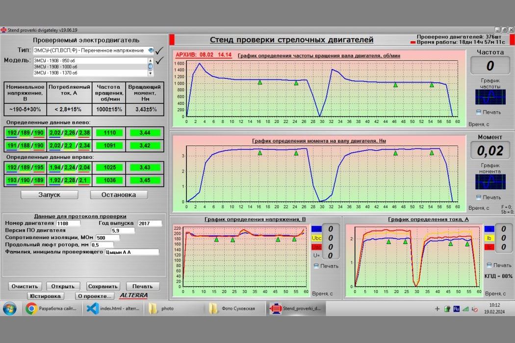
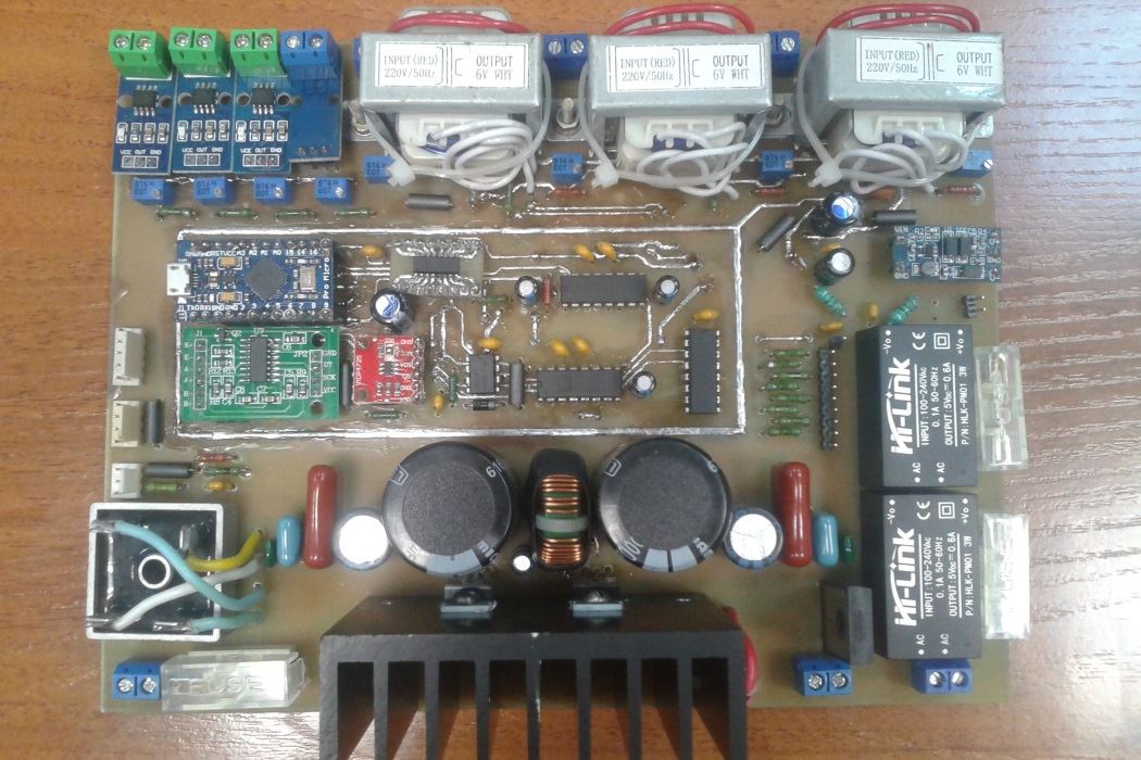
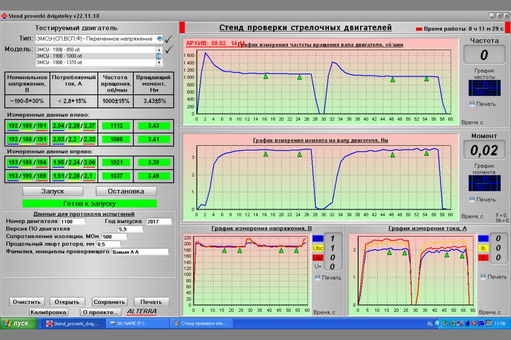
This stand allows you to perform a proper test of various models of electric motors, both with constant and alternating voltage. The test is initiated using a specially designed software application. The controller then executes a program of measurements and motor rotations, first clockwise and then counterclockwise. The black motor in the photo is the "Brake" motor, which is connected to the motor being tested. During operation, the controller gradually increases the voltage on the brake motor's winding, resulting in the braking of the armature. The "Brake" motor's housing is suspended and can rotate on the armature. A load cell is attached to the body, which is in turn attached to the stand frame. When the braking moment is created, the "Brake" housing begins to press on the load cell, and the controller receives the current braking moment value. The controller continuously adjusts the braking moment required for each type of electric motor being tested. The speed of the motor shaft is measured using an infrared sensor. The voltage and current are also measured. The data is transmitted to the PC via USB. There is a database of the nominal values for all motors. If the measured value falls within the tolerance of the nominal value, it is displayed in green, otherwise it is displayed in red.
After completing the measurements, you can print the test report or save the measurements by entering additional data.
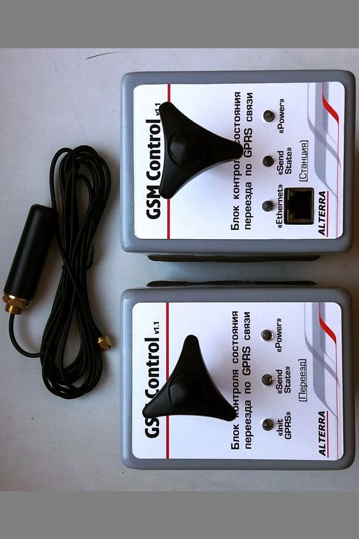
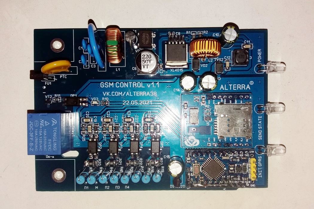
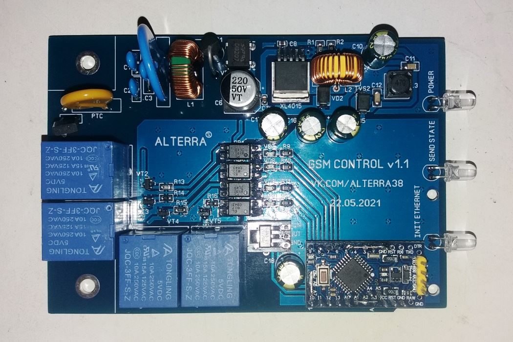
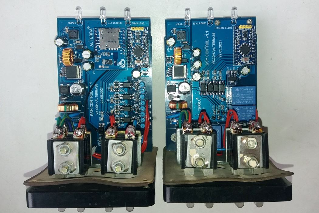
GSM Control - GPRS communication device status control system.
Due to the remoteness of the facility or the lack of technical capabilities or cables, it is not possible to monitor the condition of all STS facilities using the traditional method of the ChDK, APK-DK, or other monitoring systems.
One example is the relays within the city limits, remote from the stations. The task of this project is to organize the control of the relays condition through GSM communication.
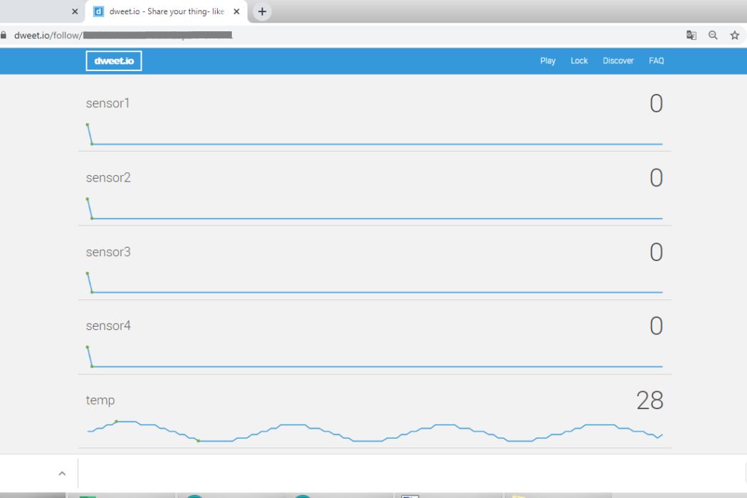
The system consists of two electronic units, one of which is installed in the crossing control room, and the second in the relay room at the EC station. A SIM card is installed in the unit at the crossing, and the other unit is at the station, connected to the Internet via Ethernet or Wi-Fi. The status information is displayed on the remote control board of the chipboard (closure, accident and non-operation).
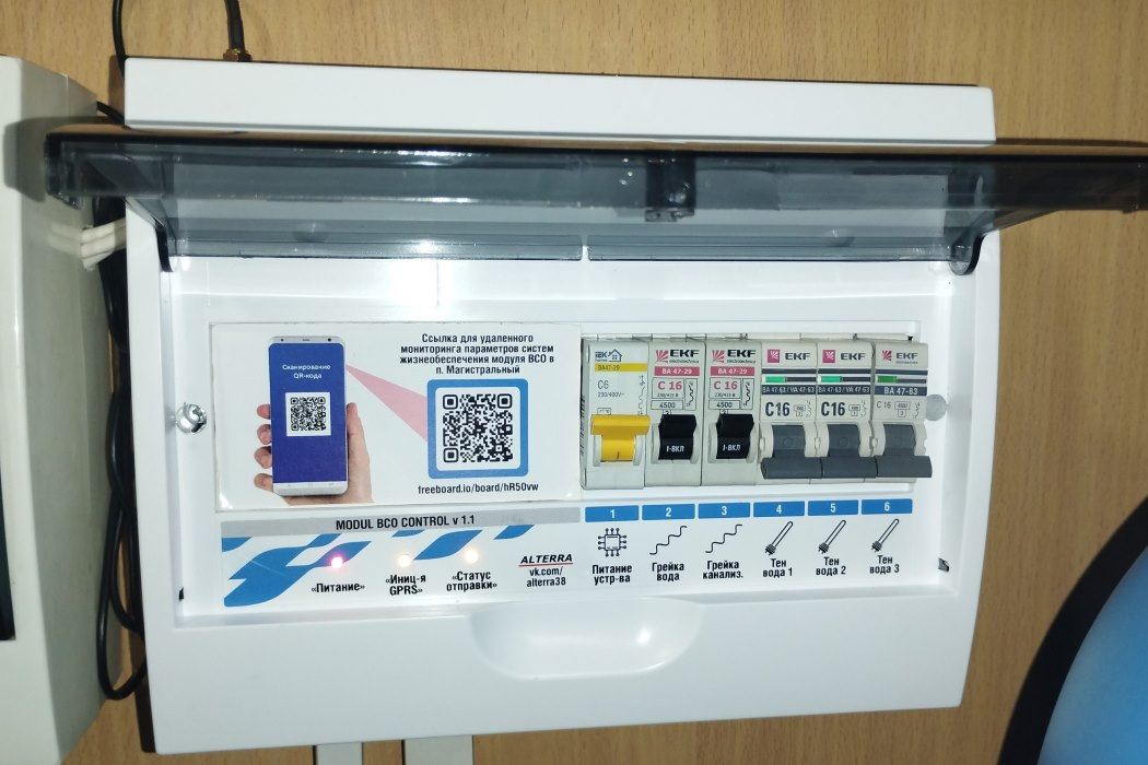
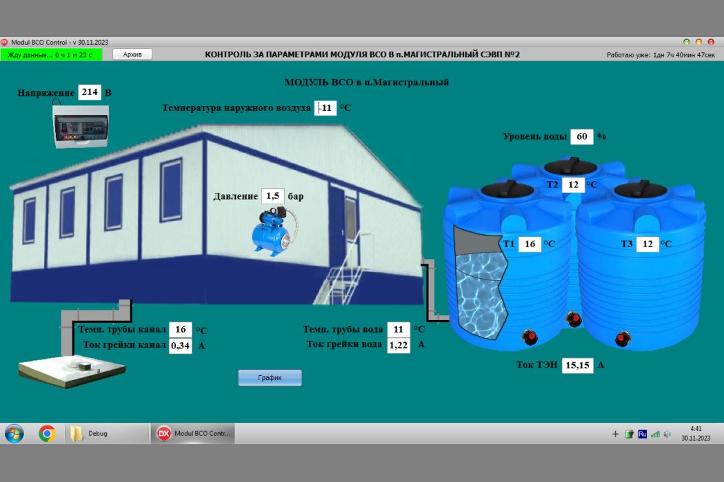
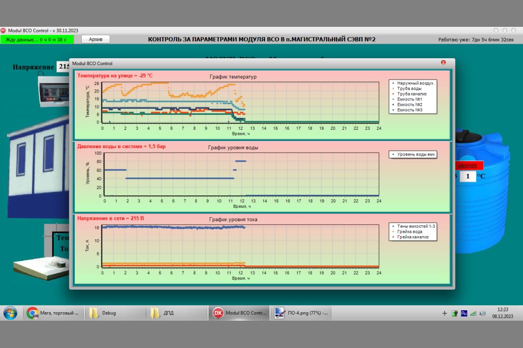
The project allows you to control the parameters of the life support systems in a small dormitory module, including:
- the voltage level in the network;
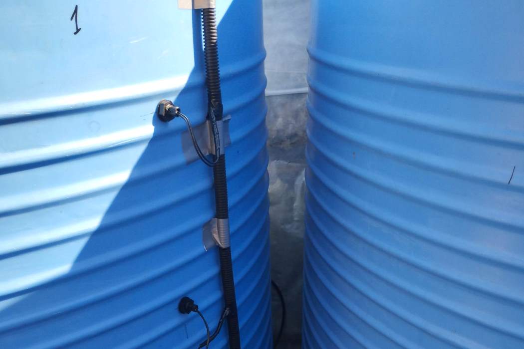
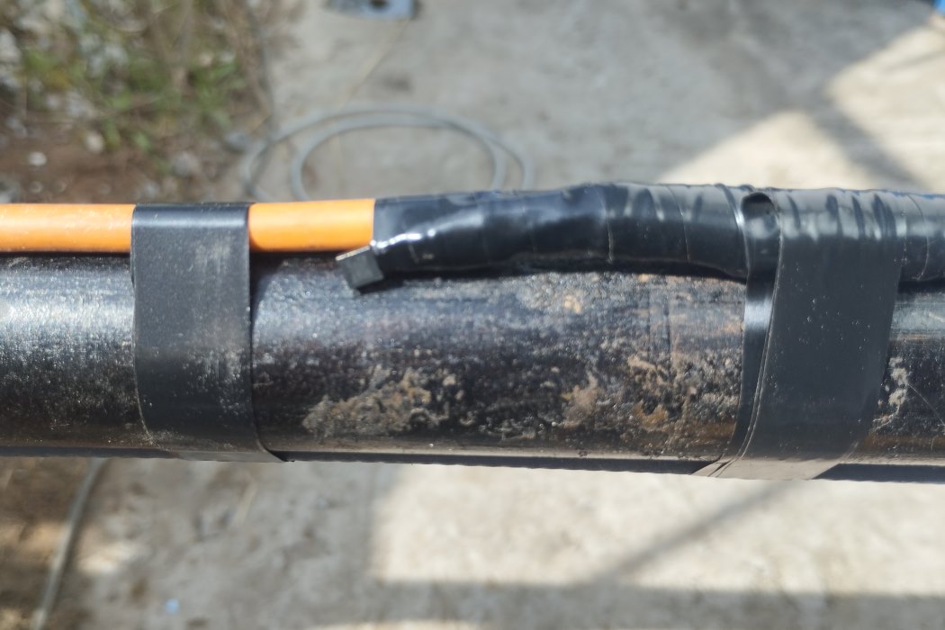
- temperatures of the outside air, three containers, and water supply and drainage pipes;
- the water level in the tanks;
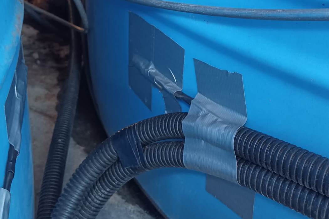
- current consumption of heating cables for external water supply and sanitation systems;
- current consumption of heating elements in water containers;
- the pressure level of the pumping station.
Monitoring of system parameters is necessary due to the large distance of the facility and for timely taking measures to restore the systems to working order.
The software allows you to archive data, output an alarm in case of exceeding the permissible limit of values.
ALSignal - Mobile complex for measuring parameters of ALSN (Automatic Locomotive Signalling). Completely redesigned the main control board, changed the element base, metal housing, added new functions. This is a complex with convenient software and mobility. You can get on any train, electric locomotive, motor locomotive and measure the ALSN code on the stage or station, and not wait half a year for the laboratory car to pass. This is especially necessary when there are failures in the ALSN, and there is simply nothing to measure such things. When measuring from the locomotive cabin, the graphs show the ALSN code in the form of a sinusoid and failures in areas with magnetized rails, equalization jumper connections, and traction substations. They also display the asymmetry of the traction current and other parameters that cannot be measured while stationary on the track. This system is similar to the Mikar system, but it offers the advantage of mobility, convenience, and flexibility for measurements, which is crucial for the maintenance staff of the signaling system.
The complex consists of receiving coils, which must be attached to the receiving coils of the locomotive, a receiver unit for primary processing and filtering of the signal, and a laptop with software. The coils are connected by a shielded wire to the signal reception unit, and measurements are taken in the rear cabin of the locomotive.
This is perhaps the only convenient option for visualizing the ALSN coding processes and equipment diagnostics.
The system allows you to:
1. Record the signal from the receiving coils;
2. Archive data, and after work, you can run the Archive to view the data in detail;
3. See the signal before the filter (signal in the RC);
4. See the signal after filtering (evaluate what comes to the locomotive devices - BS-DA);
5. The program calculates each pulse and interval (the time must be within a certain range). If the parameters exceed the normal range, a red cross is displayed on the current graph;
6. Based on time, recognize the type of KPTSh (KPTSh No. 5 or 7, which should be alternated constantly) and thus identify the erroneous installation of two identical KPTSh in a row;
7. The program calculates the current value of each pulse (the current must be within certain limits);
8. Based on the current value, it plots a current graph (at the bottom of the program window);
9. The program, based on the number of pulses in the code cycle, colors each cycle with the corresponding color (green, yellow, red-yellow, white), which is displayed on the locomotive traffic light in the train driver's cabin. In the image below, the program displays a colored bar, indicating that the train is catching up with the preceding train and changing its color from green to yellow. This is also useful for analysis, as when there are code errors, the program will mark the code cycle with white color, making it easier to identify the problematic area.
The device is capable of measuring the ALSN code at frequencies of 25Hz, 50Hz, and 75Hz. The program has many settings, including the ability to change the colors of the graphs and program windows, as well as to display additional graphs, such as the envelope graph (orange) or the pulse relay graph (green). The program also includes a battery charge level indicator.
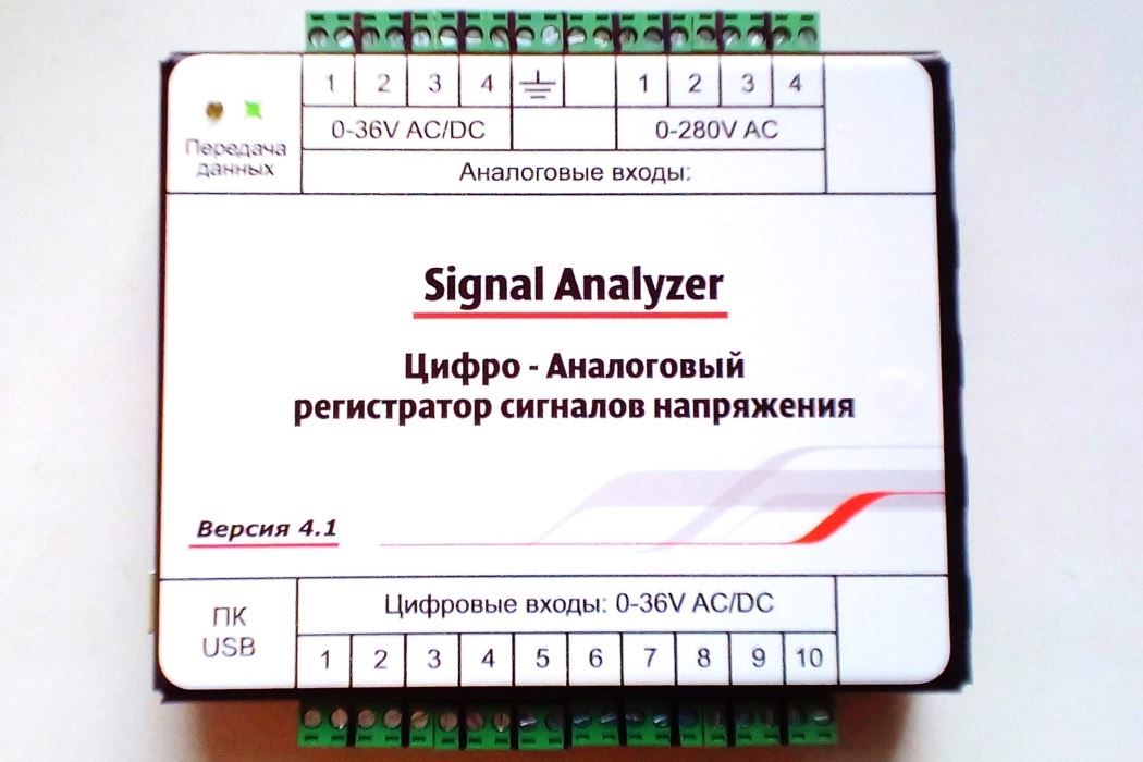
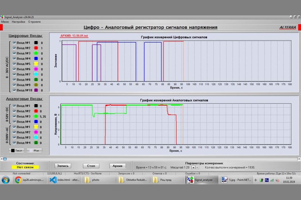
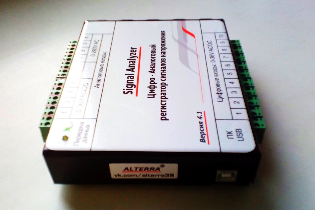
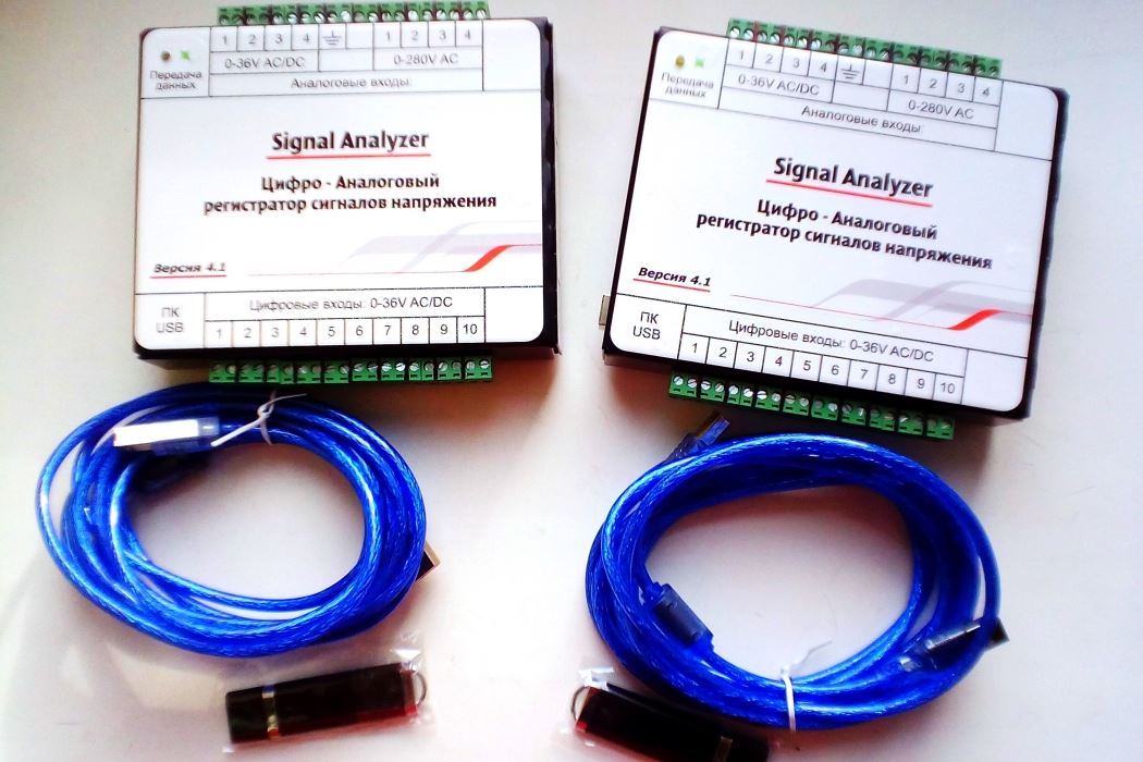
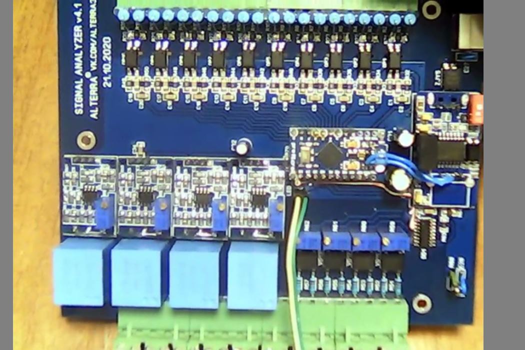
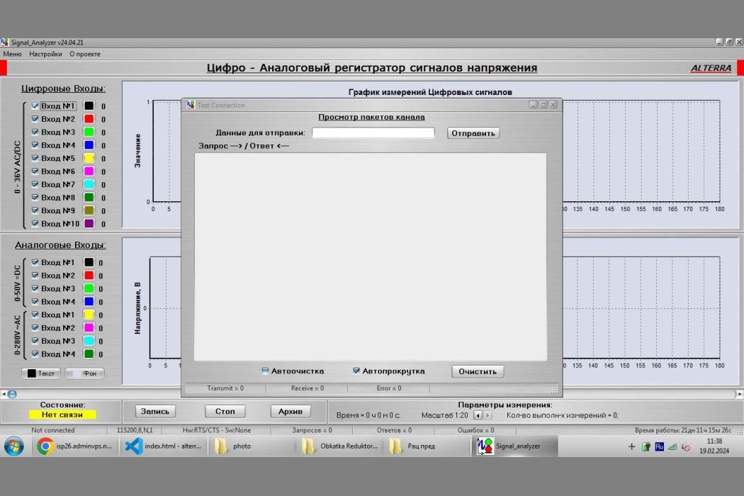
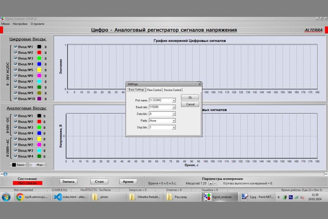
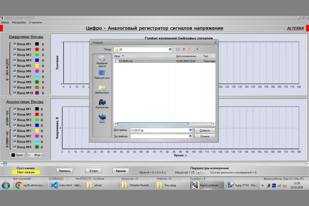
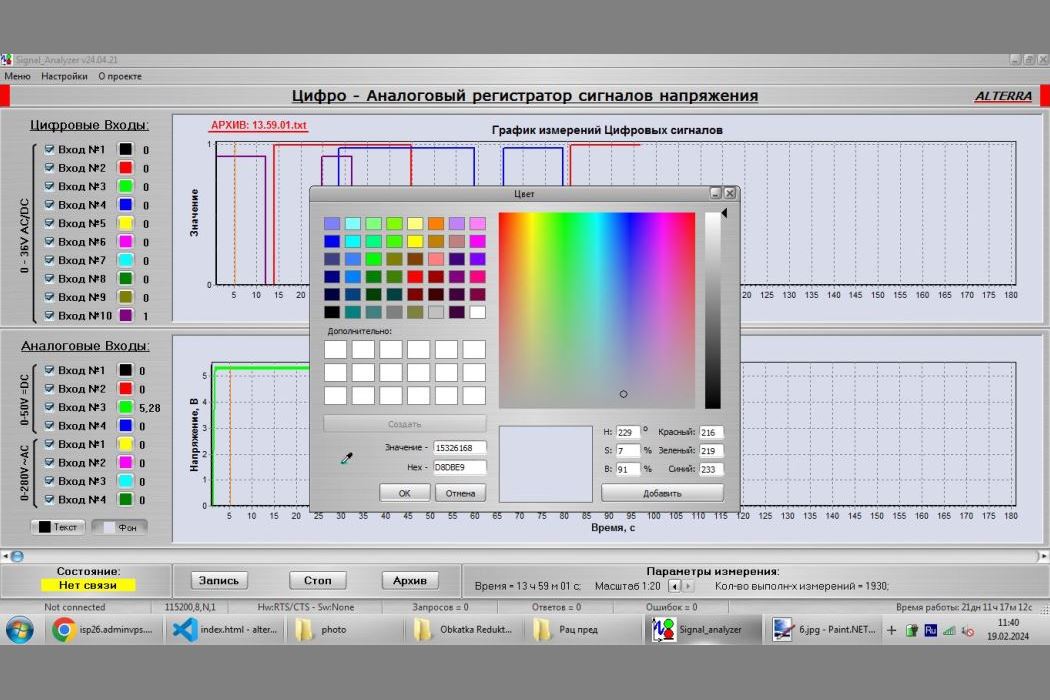
Signal Analyzer - Digital-Analog voltage signal recorder. The device and PC are galvanically isolated, electromagnetic interference protection is improved, and a reliable iron case is made. 4 high-voltage analog inputs for measuring voltage up to 280V have also been added.
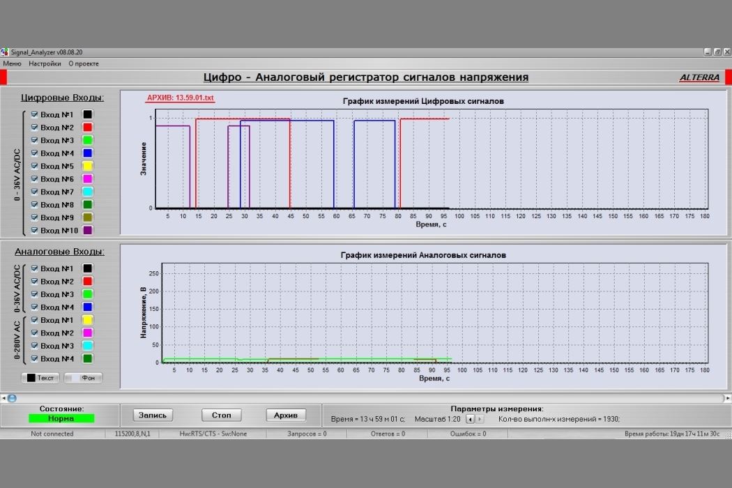
The device allows you to record voltage data of the circuits connected to it on a PC (laptop) and is designed to monitor the level and presence of voltage in electrical circuits where it is necessary to determine the cause of a malfunction. In complex electrical circuits, various control circuits that need to be monitored are selected, and the device is connected to them. There are 10 digital inputs (the presence of voltage on a specific input is converted to a logical one, and the absence is converted to a logical zero) and 8 analog inputs (the average value of signal voltages). On the PC, the recording is turned on and the voltage data is continuously recorded in the archive. If a fault occurs, you can refer to the recorded data and use the signal level and time to determine which circuit failed. The microcontroller polls all sensors every 50 ms (20 times per second). A specially designed program on the PC allows you to view voltage graphs while recording is on, view archived data, zoom in for a closer look, change the color of graphs, backgrounds, and text, and enable or disable different graphs.
The project of the Automated Stand for testing of arrow engines of various types has been completed. In order to properly test an electric motor, it is not enough to simply turn it on and measure the voltages, currents, and shaft rotation speed. It is necessary to create a load, provide resistance to the rotation of the tested motor's shaft, and perform all necessary measurements in the loaded mode. Each type of electric motor should be loaded with its own torque. Previously, in KIPs, either the motor was loaded formally and manually, or it was not loaded at all, and in both cases, the electrical parameters were not accurately recorded.
This stand allows you to perform a proper test of various models of electric motors, both with constant and alternating voltage. The test is initiated using a specially designed software application. The controller then executes a program of measurements and motor rotations, first clockwise and then counterclockwise. The black motor in the photo is the "Brake" motor, which is connected to the motor being tested. During operation, the controller gradually increases the voltage on the brake motor's winding, resulting in the braking of the armature. The "Brake" motor's housing is suspended and can rotate on the armature. A load cell is attached to the body, which is in turn attached to the stand frame. When the braking moment is created, the "Brake" housing begins to press on the load cell, and the controller receives the current braking moment. The controller continuously adjusts the braking moment required for each type of motor being tested.
The speed of the motor shaft is measured using an infrared sensor. The voltage and current are also measured. The data is transmitted to the PC via USB. There is a database of the nominal values of all motors. If the measured value falls within the tolerance of the nominal value, it is colored green, otherwise it is colored red.
After completing the measurements, you can print the test report or save the measurements by entering additional data.
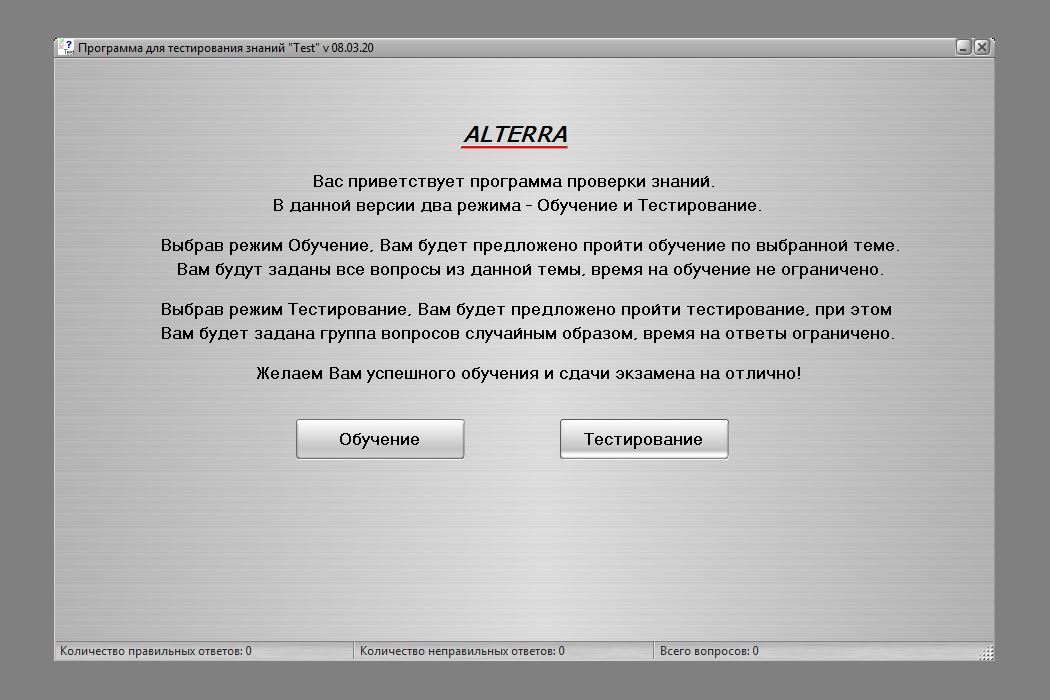
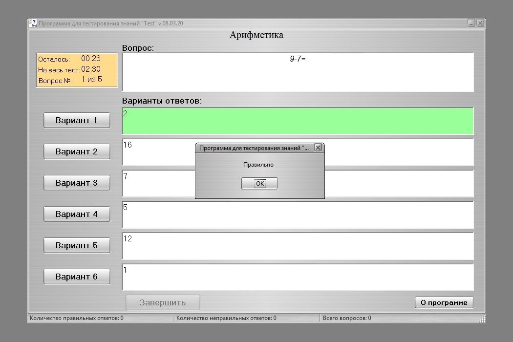
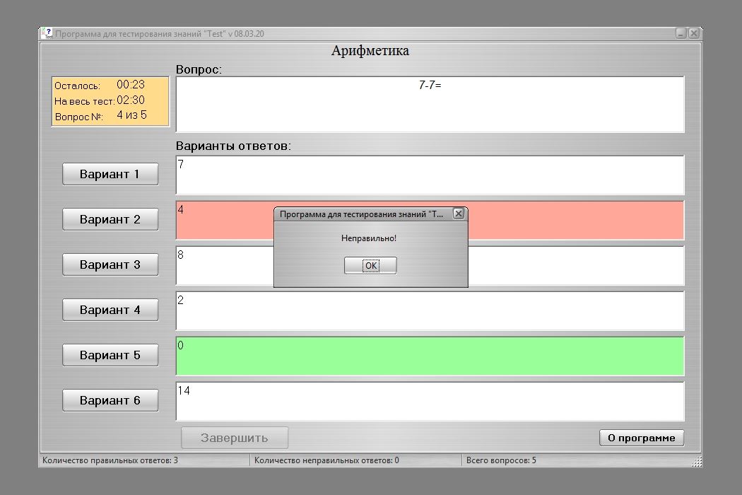
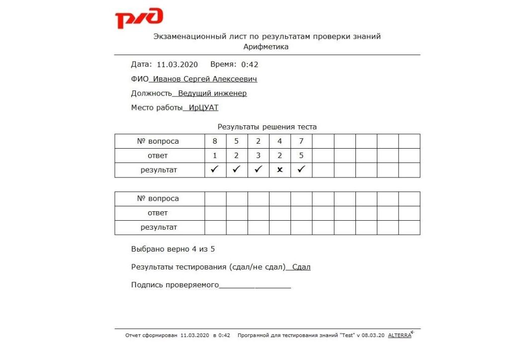
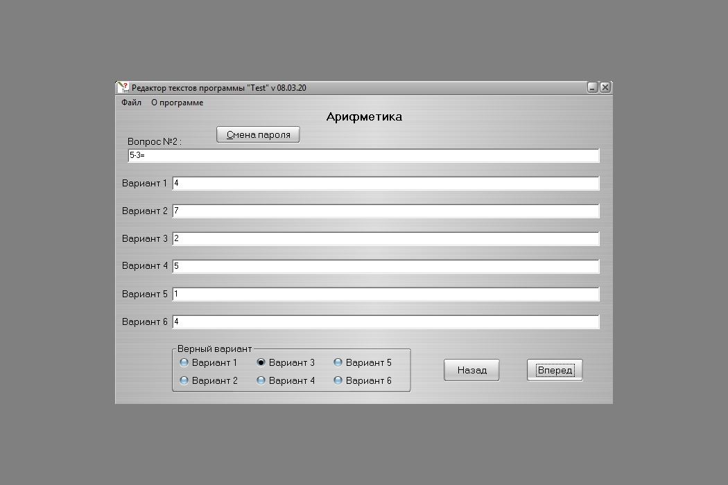
The "Test" v 08.03.20 project has been completed for the needs of JSC Russian Railways. This is a simple program for training and testing the knowledge of the company's employees. The software includes the "EditTest" v 08.03.20 test file editor, which is necessary for creating a test file on any topic. Using the "Test" v 08.03.20 program, employees can more effectively study various topics (Training section) and take exams on them (Testing section). At the end of the test, you can view and analyze your mistakes, as well as print the test results.
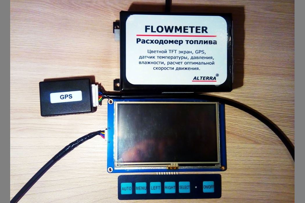
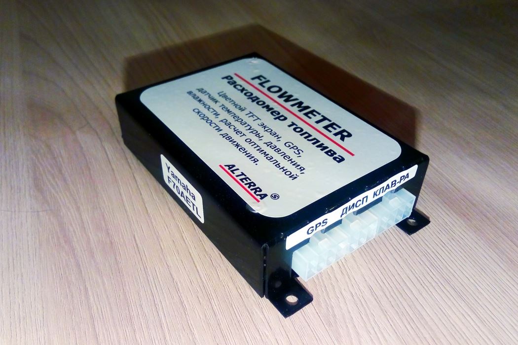
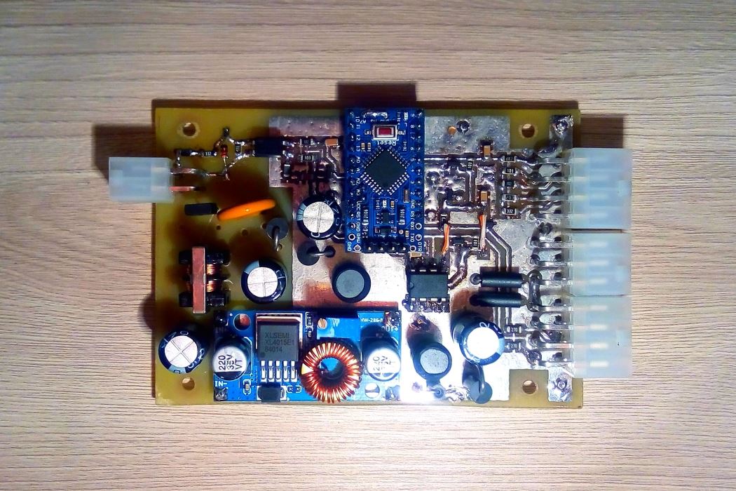
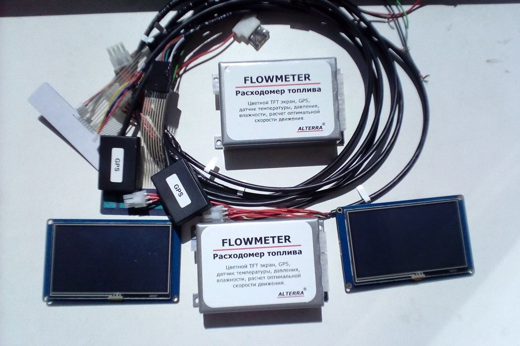
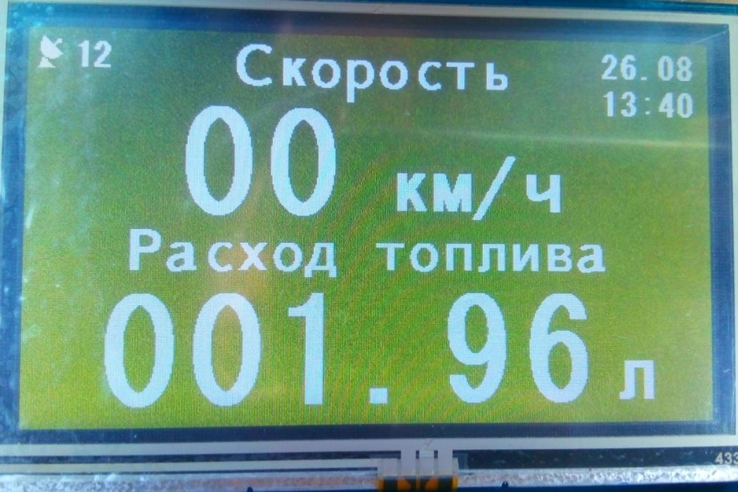
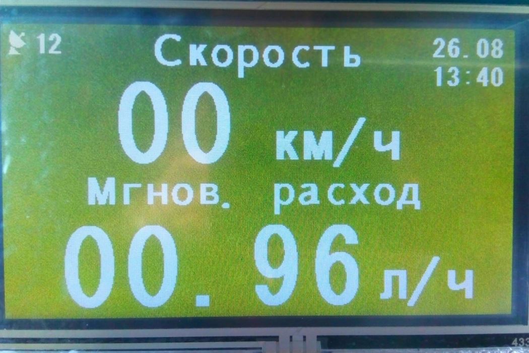
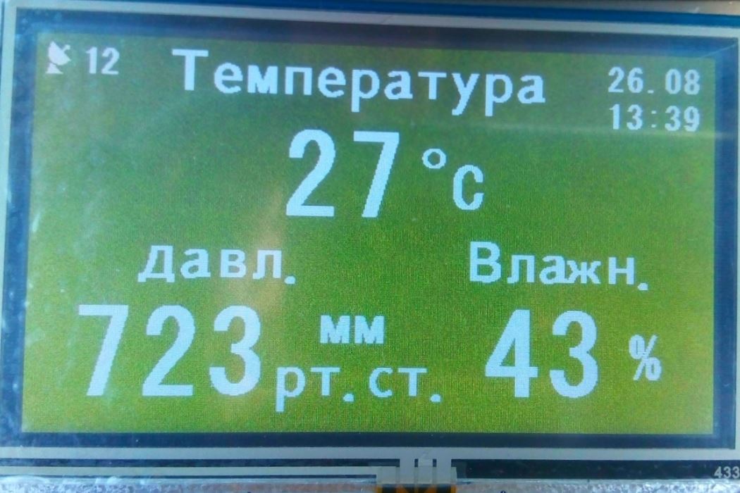
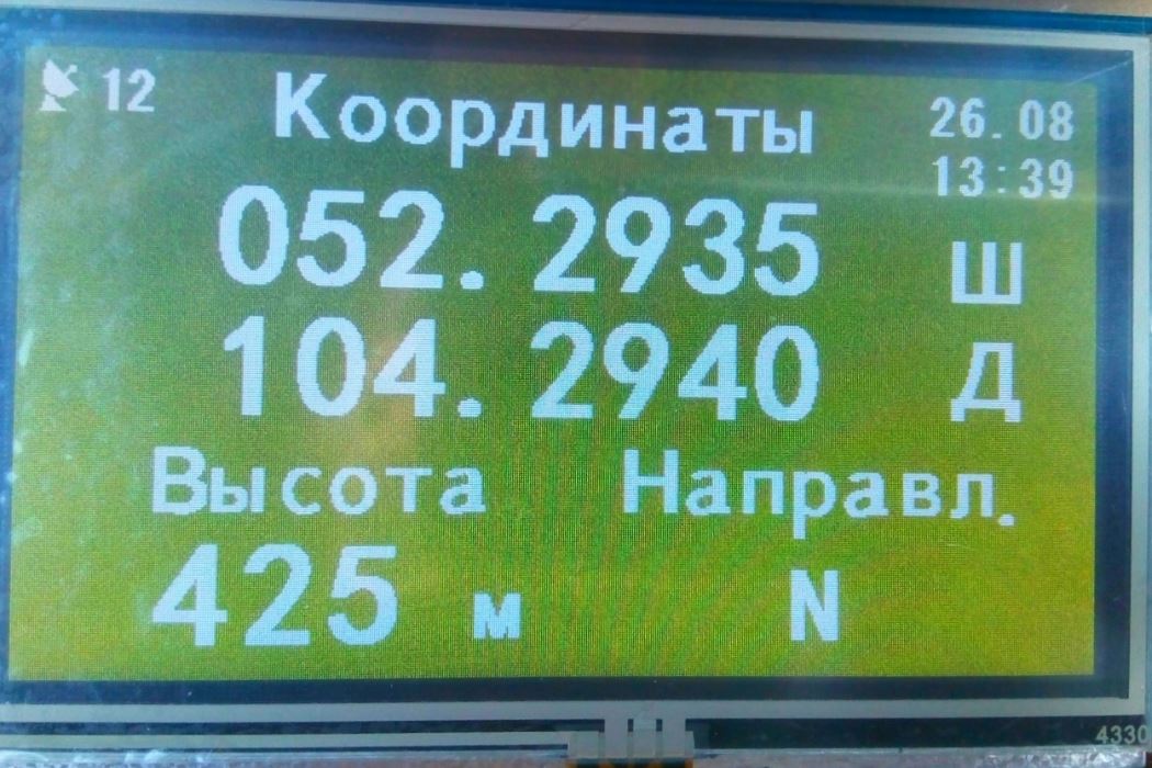
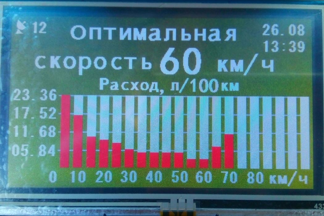
FLOWMETER - Fuel flow meter. The device is designed to measure fuel consumption and can work with any type of engine with an injection fuel system. It can be used in both automotive and marine applications where fuel consumption and speed control are important. The device features a color TFT display (touch screen), a GPS sensor, a temperature sensor, a pressure sensor, a humidity sensor, and a 6-button keyboard. It is capable of displaying instantaneous fuel consumption (l/h), total consumption (l), engine speed (rpm), travel speed (km/h), mileage (km), air temperature (C), pressure (mm Hg), humidity (%), location coordinates (W,D), altitude (m), and direction of travel (NNW). The controller remembers the fuel consumption at different speeds and calculates the optimal speed based on fuel economy. The signal is received from the engine injector, processed by the microcontroller, and the fuel consumption is calculated. When the vehicle stops, the data is automatically stored in the device's memory.
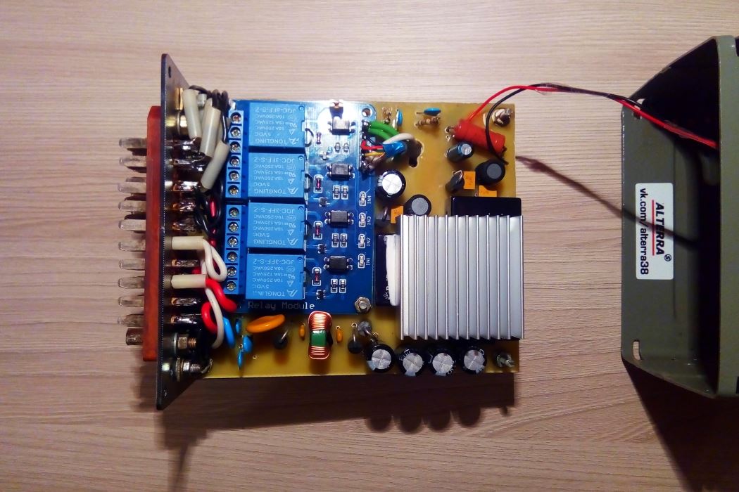
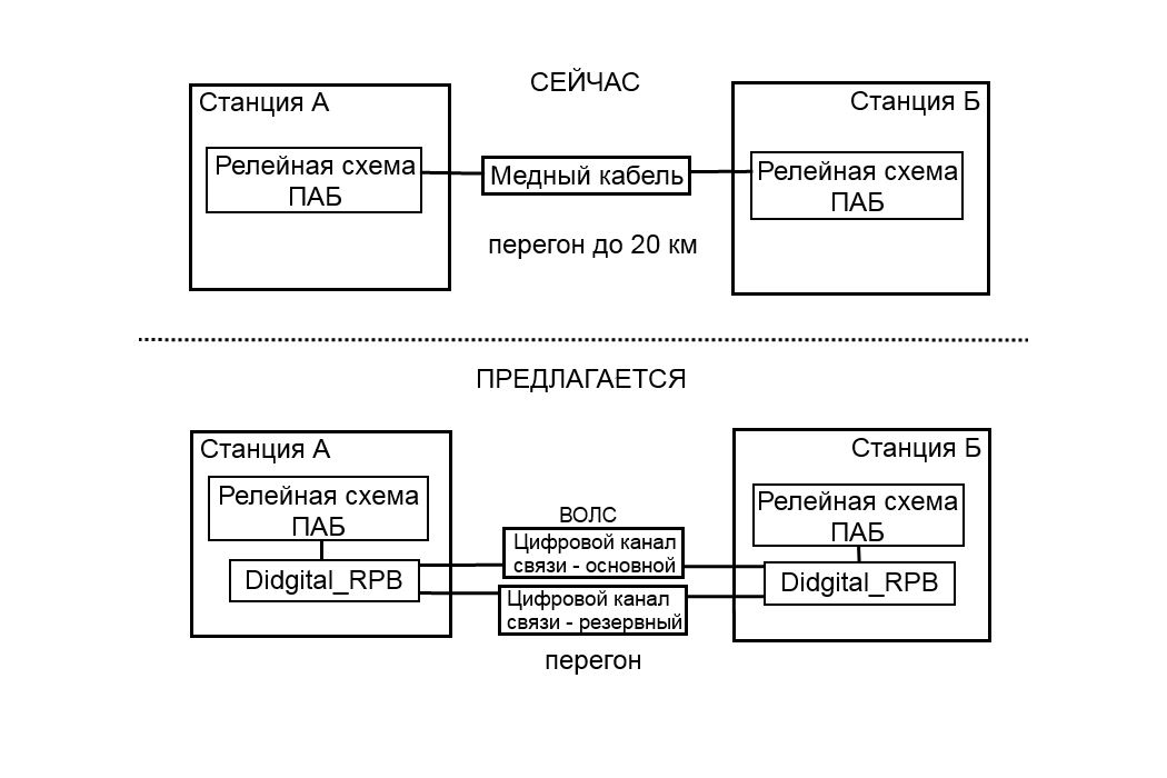
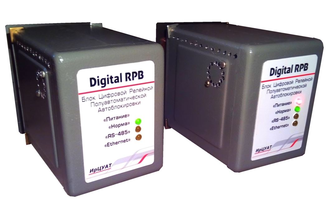
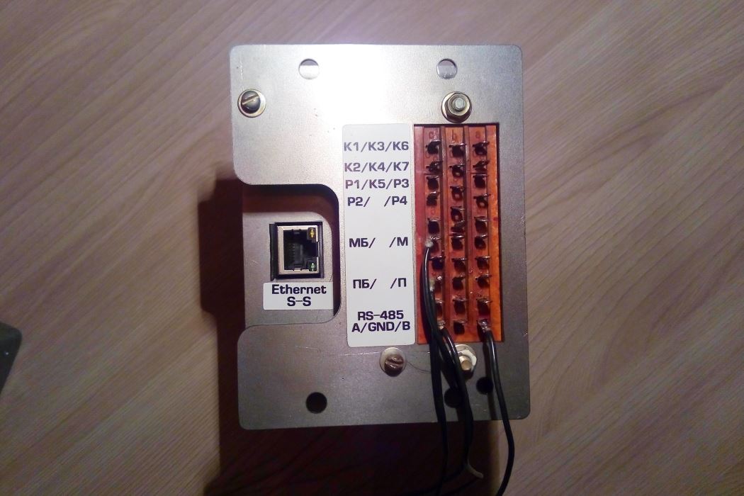
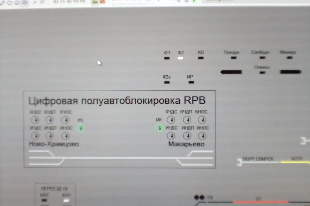
Digital RPB - Digital Semi-Automatic Auto-Block for Russian Railways. These units are installed at neighboring stations that limit the section with semi-automatic auto-block, are connected to the existing relay scheme, and transmit data about the scheme's operation to each other via fiber optic cables or other digital communication sources.
The previously used copper cable, which was necessary for the circuit to work, is no longer needed. It is physically buried along the railway track throughout the entire section. Maintaining it is an expensive and complex process. Digital communication channels are more efficient and reliable.
The Digital RPB units have two communication channels: the main one is RS-485, and the backup is Ethernet. If either communication channel fails, the unit automatically switches to the other, as shown in the video.
The transmitted data is protected by a CRC checksum, control of the number of received bytes in the message, matching of the initial and final message markers, receipt of only one command, receipt of the direct and inverse command code, control of the command reception by another station, and control of the status of all actuators.
The arrow gearbox has a friction clutch, which is necessary for operation when the arrow points are abruptly stopped (if an object gets in the way). When replacing the friction discs with new ones or when overhauling them, it is necessary to grind them to ensure stable clutch operation.
This stand was created for this purpose. The stand is fully automated and controlled by a specially designed program. The microcontroller controls the activation of the electric motors, reverses the direction of rotation, receives data on the lapping force of the friction discs in the gearbox from the load cells, and transmits and receives data from the PC. The required lapping force is set, and if the force does not change by more than 10% by the end of the lapping program, it indicates that the discs have been lapped. The program consists of 5 cycles, each cycle is the inclusion of the electric motor for 2 minutes to the right, then stop and include the electric motor to the left. Pause 30 minutes is necessary for cooling of the discs and gearbox during the run-in. All measurements are saved in the archive, which can always be viewed, as well as the run-in protocol of the gearbox is formed.
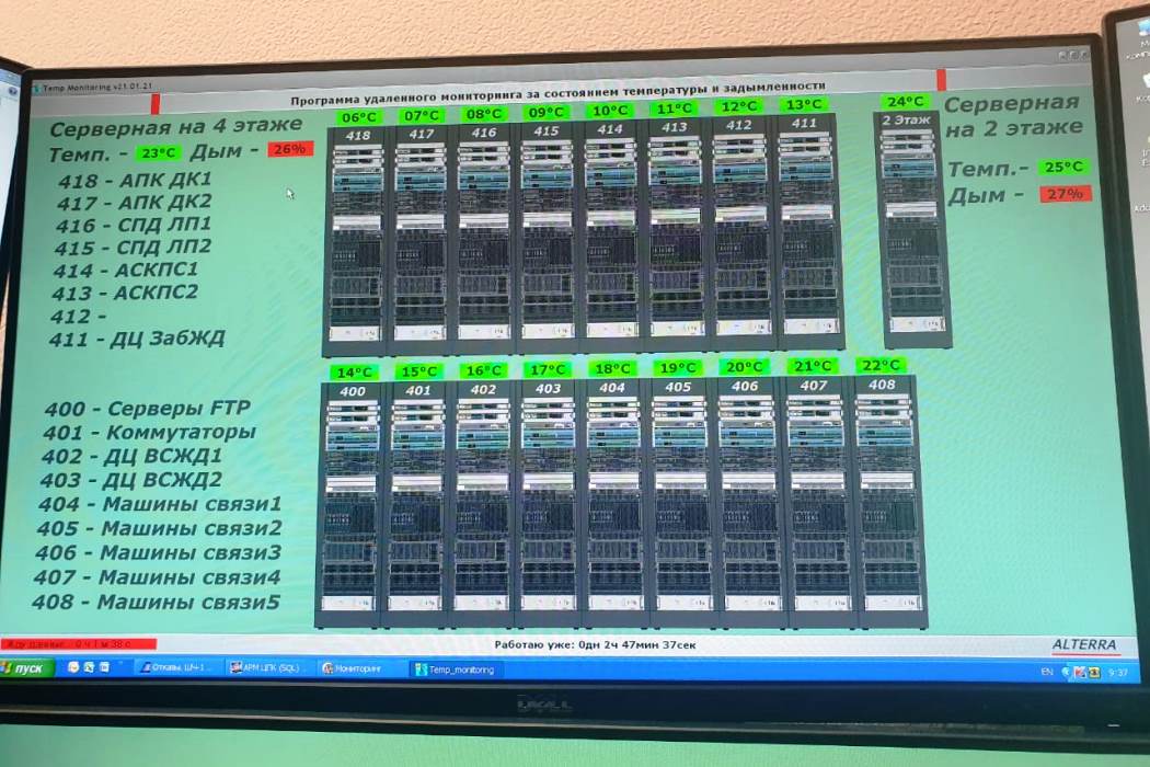
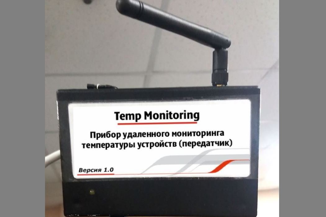
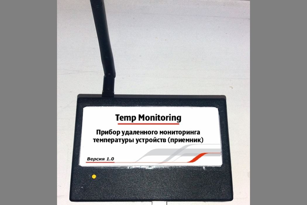
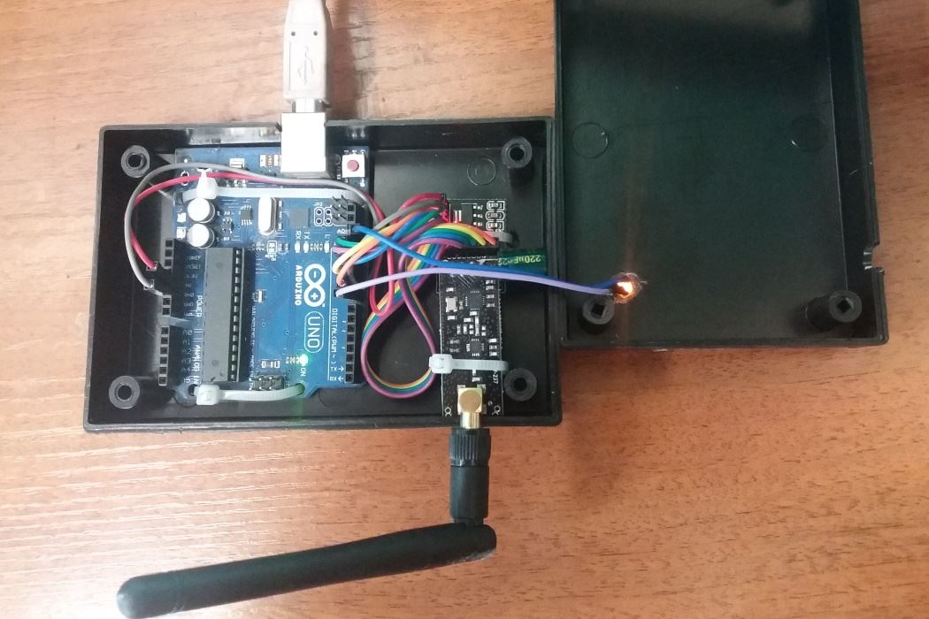
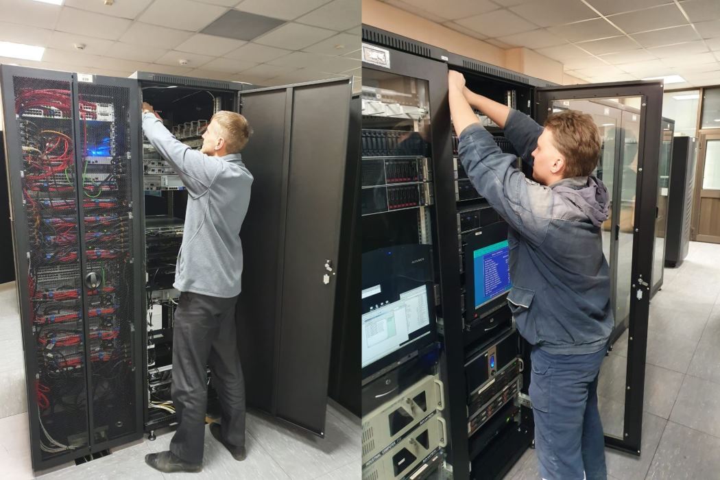
Temp Monitoring is a project for implementing temperature control in server cabinets. The equipment in these cabinets heats up during operation, and it is necessary to periodically inspect the racks to monitor the temperature.
We offer to equip these racks with microprocessor temperature sensors for remote monitoring of the temperature inside the cabinets. The temperature control is displayed on the engineer's monitor.
The data is read and updated every 5 seconds. If the temperature level rises to an acceptable level, the green cells in the program window will turn yellow, indicating that the equipment needs to be checked. If the temperature level continues to rise, the cells in the program window will flash red and yellow, alerting the on-duty personnel. Once the equipment is restored, the alarm mode can be reset by clicking on the cell.
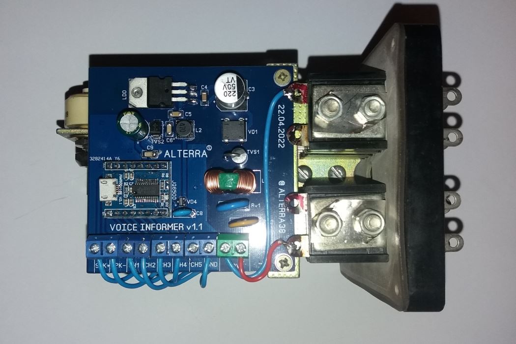
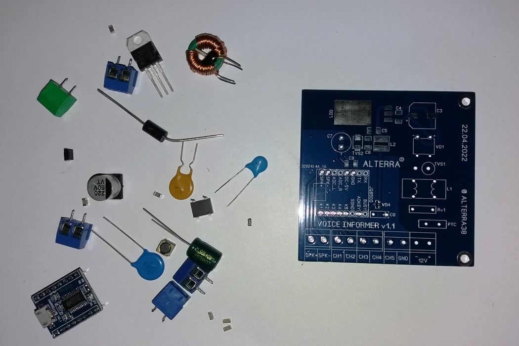
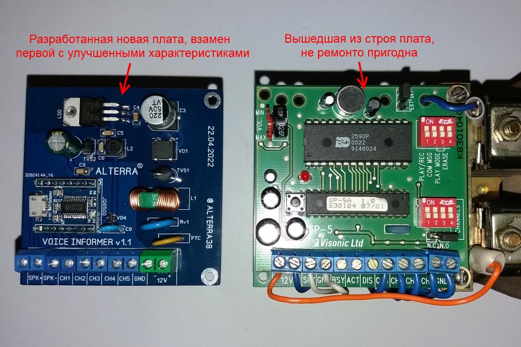
Not all railway stations are equipped with voice informers to alert workers on the tracks about approaching trains. Alternatively, the informers may have been damaged over time. There are stations where trains suddenly appear from around a corner at high speeds, causing the station attendants to fail to warn workers in time to leave the tracks...
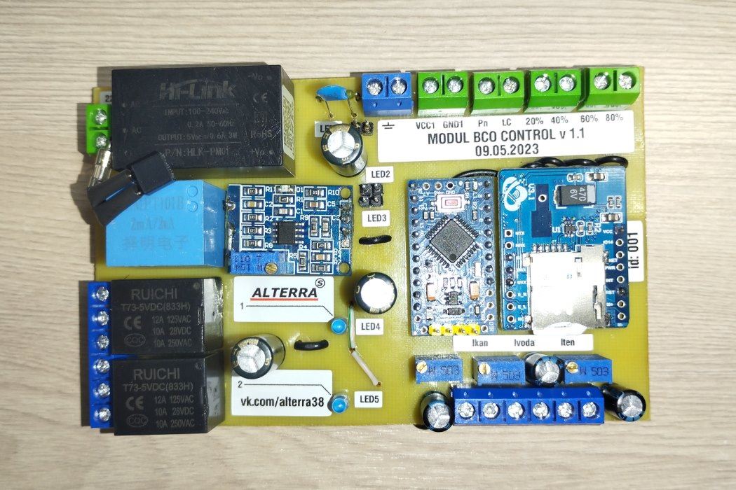
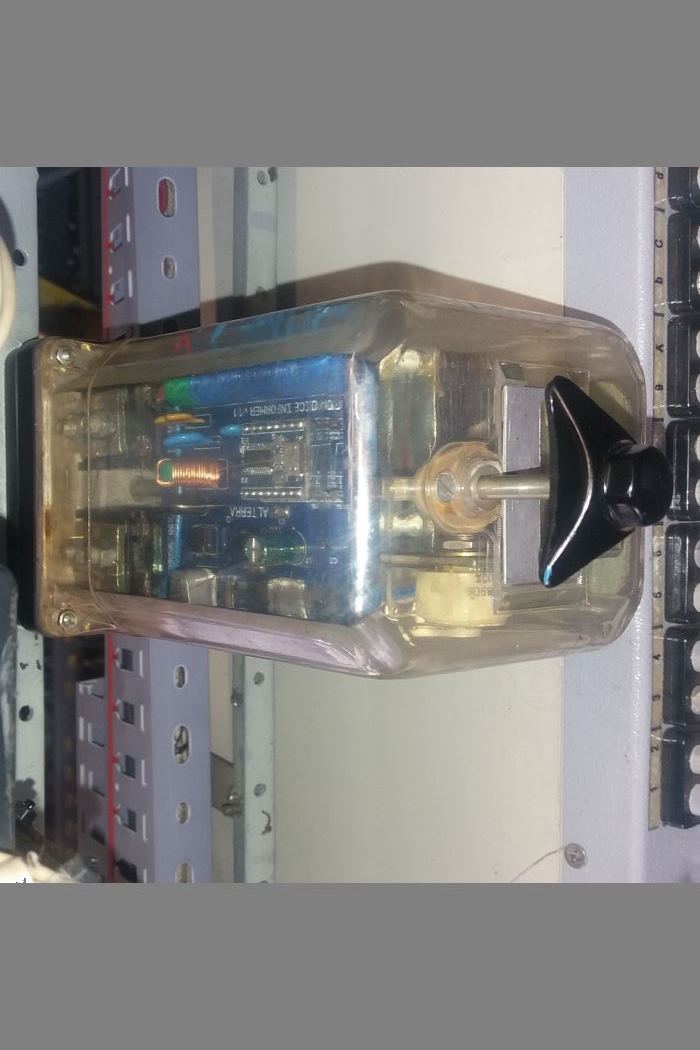
We offer you an upgraded voice informer – Voice Informer v1.1, which will solve the above-mentioned problem. The voice informer is based on a new element base, similar to the SP-5 boards that have failed and cannot be repaired. The unit is completely interchangeable with the old one and can play 4 messages automatically, alerting workers to the approaching train.
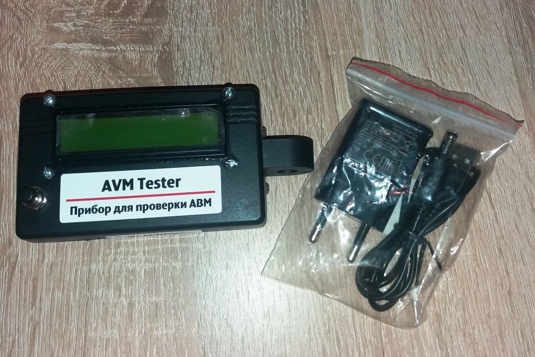
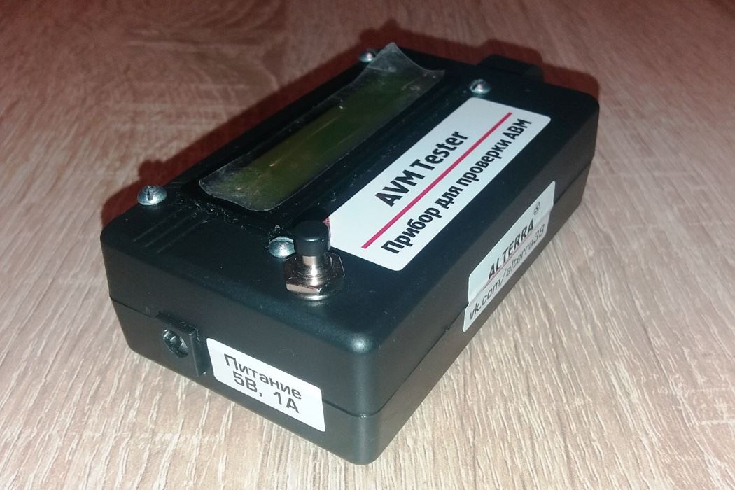
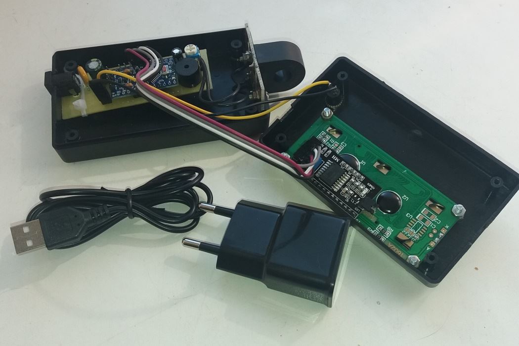
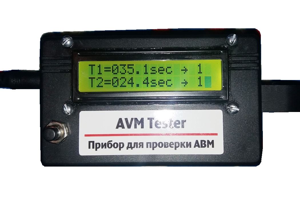
AWM Tester is a device for checking the time parameters of AWM in the remote control units of the signaling and blocking system.
According to the technological map for checking the AVM device in the RTO of the STSB distances, after inspection, cleaning, adjustment, and repair, it is required to measure the time parameters of its shutdown and startup, and for greater accuracy of the device, a series of 3 measurements of the shutdown time and 3 measurements of the startup time are made, and then the average values are calculated. The measurements are made inaccurately, manually, using an outdated mechanical method with a stopwatch.
AVM Tester will allow you to automate this time-consuming and imperfect process. This device automatically measures the time it takes to turn the AVM off and on in all three measurement series, ensuring maximum accuracy. It calculates the average time it takes to turn the AVM off and on at the end of the measurement process, freeing up staff time and increasing productivity. During the measurement process, the RTO electrician can inspect and clean the next AVM device.
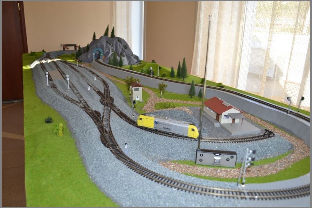
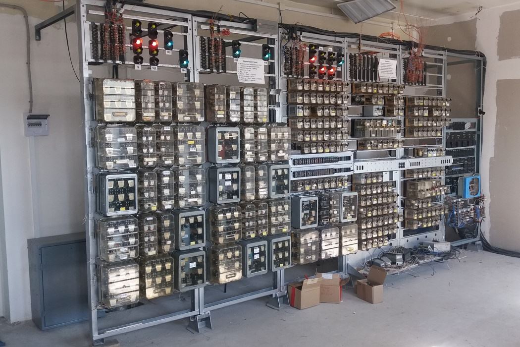
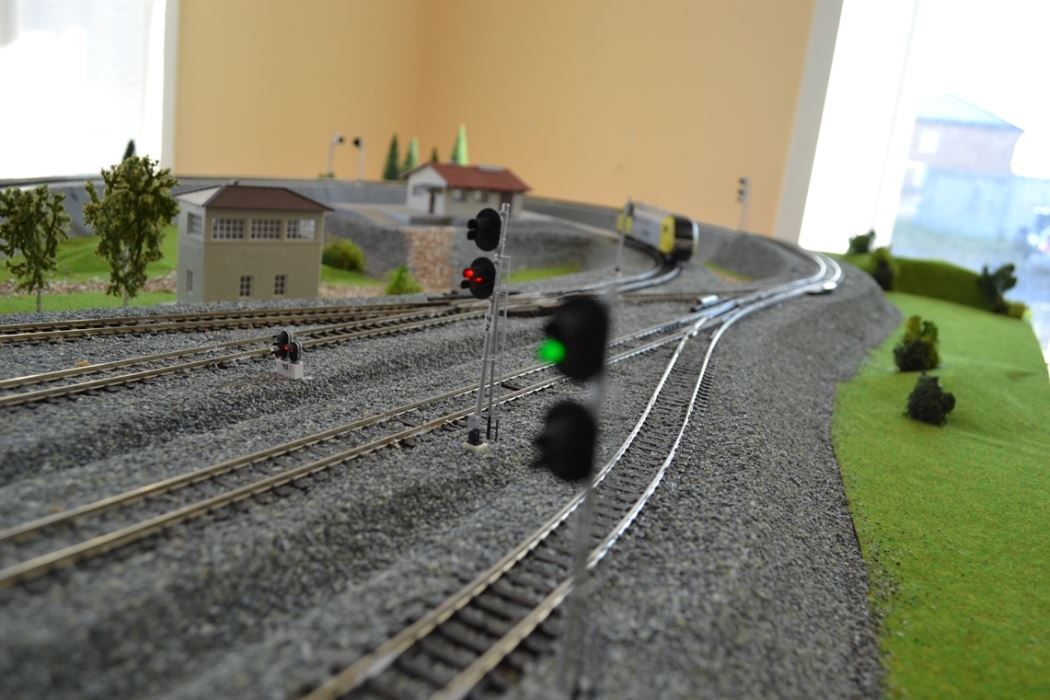
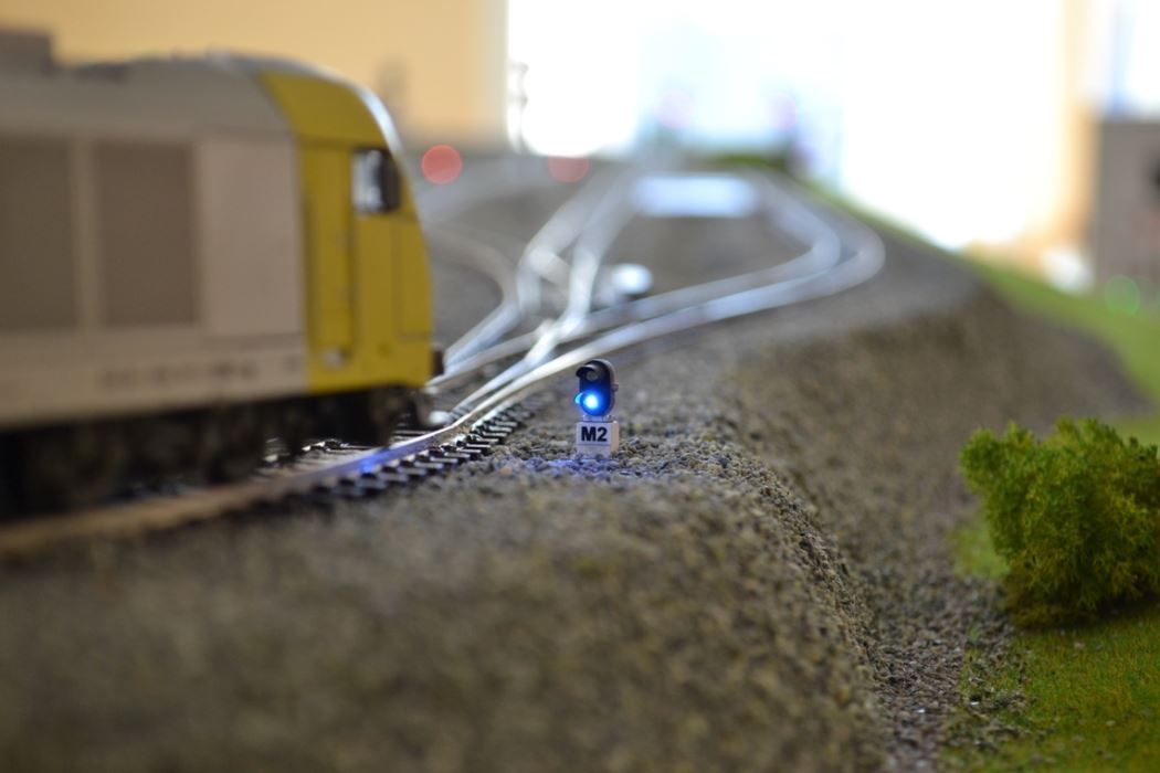
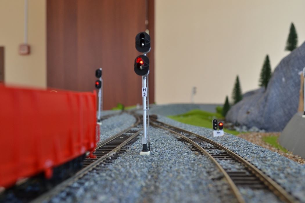
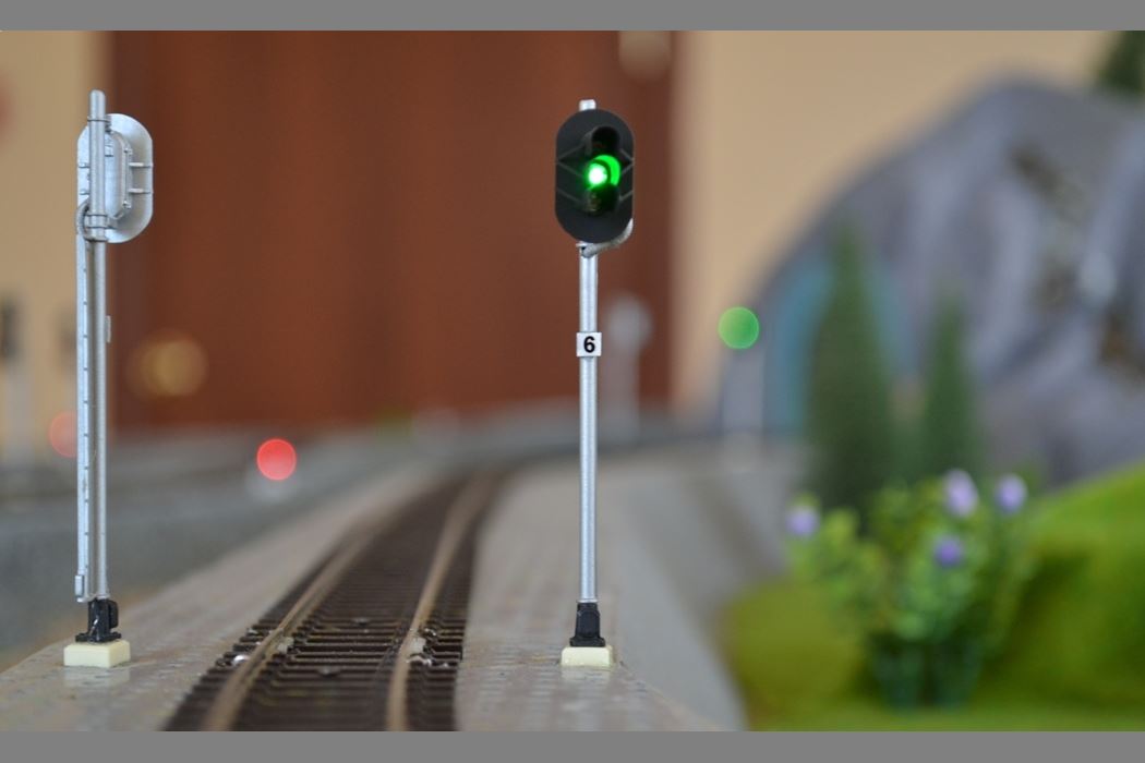
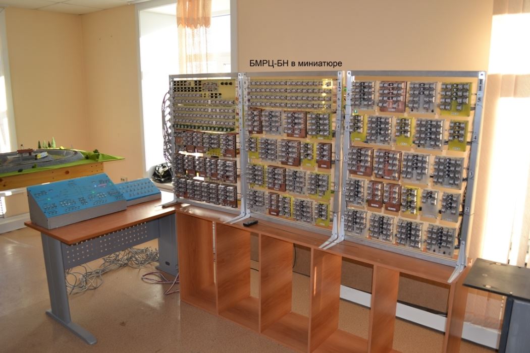
The idea of creating a unique model of a railway station equipped with a BMRC was born back in university. It took me three years to realize this idea while working as a senior electrical engineer in the railway signaling department. Yes, it was done on weekends and in the evenings, slowly and painstakingly, but it was eventually achieved. At that time, there was no concept of microcontrollers or programming; it was all about using old-fashioned relays.
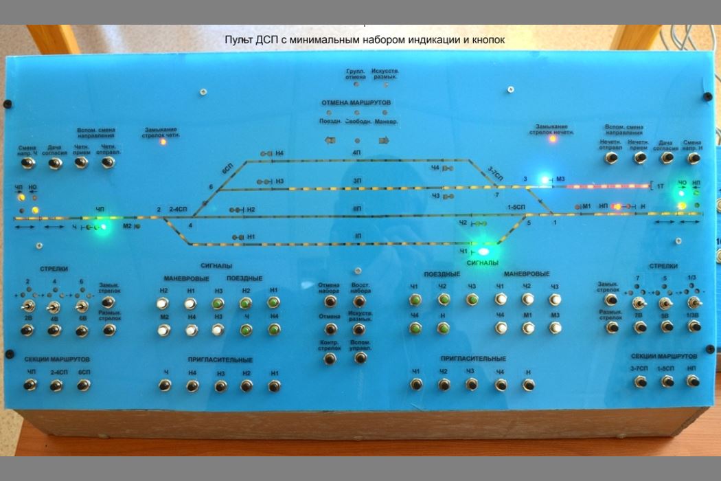
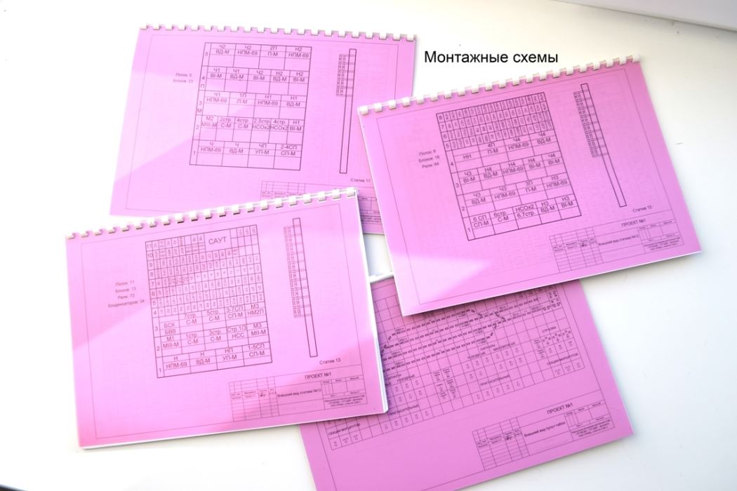
The station was designed to be a four-track station with seven switches, one siding, and a single-track section. I used standard diagrams from the textbooks. Using the Visio software, I created a block diagram and various schematics based on the layout of the tracks, switches, siding, and signals. These schematics included rail circuits, traffic light activation, switch control, automatic train control, power supply, and sectionalization. Unlike the schematics used in real railway stations, I drew my own schematics without abbreviations, with the blocks fully expanded, so that all the relays and their contacts were visible on the diagram. I thought it would be easier for the trainees to understand how they worked. As a result, the diagrams were quite large, but they were also informative. The longest diagram, about four meters long, was the diagram for setting up and dividing routes.
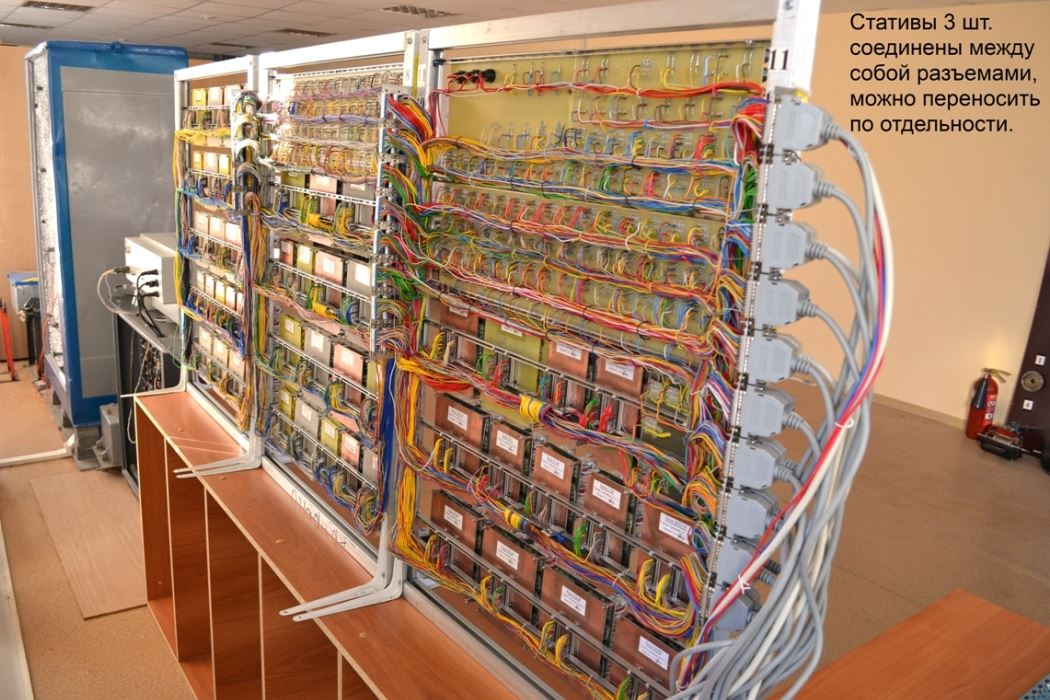
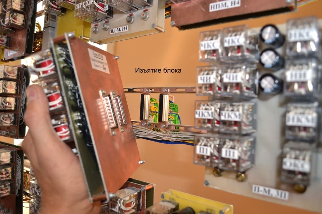
After the schematics were ready, we could start making the blocks. This required about 800 mini-relays and a lot of patience. We purchased a channel bar to make the statics. We used it to create frames with shelves. The chipboard panel was quite impressive, with all the necessary buttons for controlling the station. Creating the layout was equally challenging. Miniature rails, switches, locomotives, and wagons were also purchased on an online website, and traffic lights for the model were purchased from a craftsman in Tomsk. Friends and colleagues helped out, becoming interested in the process.
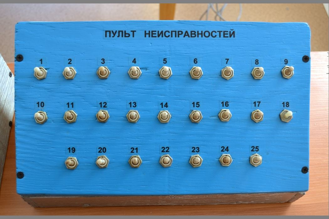
The result of the joint work was very satisfying. The created relay functioned like a real one. From the station attendant's console, the arrows included in the route are automatically transferred, and the safety conditions are pre-checked. Then, the route is closed and the signal is opened. The company's electrical engineers had the opportunity to work as a station attendant, setting various routes on the console, being a locomotive driver who drives the locomotive from a remote control console, following the route, performing maneuvers, and most importantly, the mock-up simulator simulates 25 different faults in the following circuits:
1. Faulty KNH and NKH relays – 2 pieces;
2. Faulty PU and MU relays – 2 pieces;
3. Faults in the H and NM relays – 2 pieces;
4. Faulty KS relay – 1 piece;
5. Faulty relay Vz – 1 piece;
6. Faulty CHI, NI relay – 1 piece;
7. Faults in relay C and MC – 3 pieces;
8. Faults in relays 1M and 2M – 3 pieces;
9. Faulty cancellation circuits – 4 pieces;
10. Indication malfunctions – 2 pieces;
11. Faulty relay – 1 piece;
12. Faulty LS relay – 1 piece;
13. Direction change malfunction – 1 piece;
14. Faulty arrow control circuit – 1 piece.
Signal Analyzer - Digital-Analog voltage signal recorder. The device and PC are galvanically isolated, electromagnetic interference protection is improved, and a reliable iron case is made. 4 high-voltage analog inputs for measuring voltage up to 280V have also been added.
The device allows you to record voltage data of the circuits connected to it on a PC (laptop) and is designed to monitor the level and presence of voltage in electrical circuits where it is necessary to determine the cause of a malfunction. In complex electrical circuits, various control circuits that need to be monitored are selected, and the device is connected to them. There are 10 digital inputs (the presence of voltage on a specific input is converted to a logical one, and the absence is converted to a logical zero) and 8 analog inputs (the average value of signal voltages). On the PC, the recording is turned on and the voltage data is continuously recorded in the archive. If a fault occurs, you can refer to the recorded data and use the signal level and time to determine which circuit failed. The microcontroller polls all sensors every 50 ms (20 times per second). A specially designed program on the PC allows you to view voltage graphs while recording is on, view archived data, zoom in for a closer look, change the color of graphs, backgrounds, and text, and enable or disable different graphs.
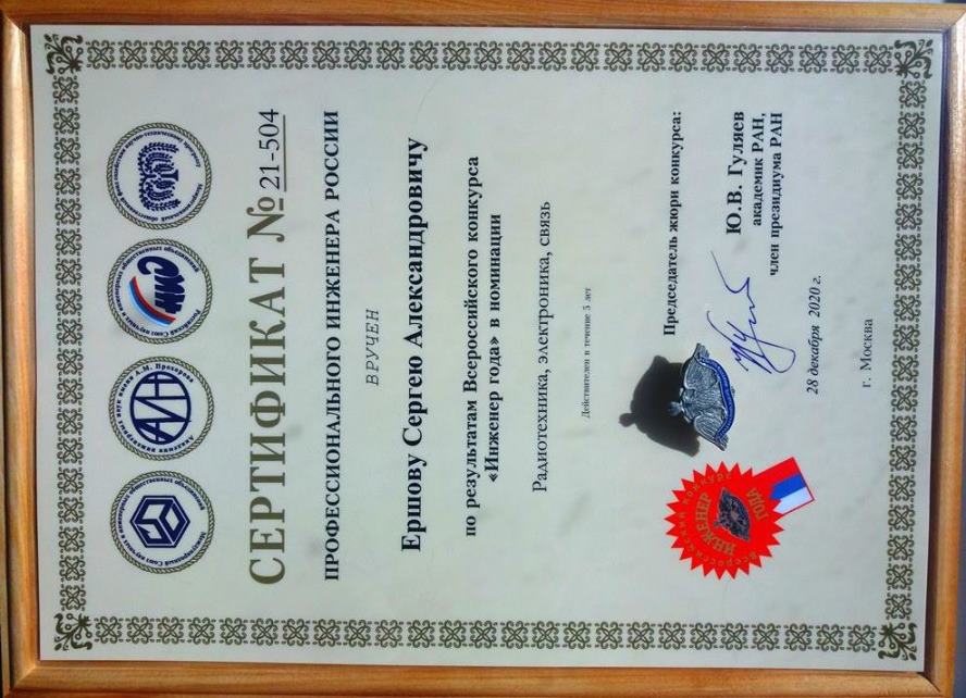
Moscow
December 28, 2020
Irkutsk
February 12, 2024
This Privacy Policy for Personal Data (hereinafter referred to as the Privacy Policy) applies to all information posted on the website at alterra38.ru (hereinafter referred to as the Website), which the Website Administration (hereinafter referred to as the "Administrator") may obtain about the User while using the Website.
1. Definition of terms
1.1. The following terms are used in this Privacy Policy:
1.1.1. "Site Administration" means authorized site management personnel acting on behalf of the site owner, the site owner, who organize and (or) process personal data, as well as determine the purposes of personal data processing, the composition of personal data to be processed, and actions (operations) performed with personal data.
1.1.2. "Personal Data" means any information relating directly or indirectly to a specific or identifiable natural person (personal data subject).
1.1.3. "Personal data processing" means any action (operation) or a set of actions (operations) performed using automation tools or without such tools with personal data, including collection, recording, systematization, accumulation, storage, clarification (update, modification), extraction, use, transfer (distribution, provision, access), anonymization, blocking, deletion, and destruction of personal data.
1.1.4. "Confidentiality of personal data" is a requirement that the Administrator or any other person who has access to personal data must comply with in order to prevent their dissemination without the consent of the subject of personal data or any other legal basis.
1.1.5. "Website User (hereinafter referred to as the User)" is a person who has access to the Website via the Internet and uses the portal.
1.1.6. "Cookies" is a small piece of data sent by a web server and stored on the user's computer, which the web client or web browser sends to the web server in an HTTP request every time the user attempts to open a page on the corresponding website.
1.1.7. "IP address" is a unique network address of a node in a computer network built according to the IP protocol.
2. General provisions
2.1. The User's use of the website implies acceptance of this Privacy Policy and the terms of processing the User's personal data.
2.2. If the User does not agree with the terms of the Privacy Policy, they must stop using the website.
2.3. This Privacy Policy only applies to this website. The Administrator does not control or assume responsibility for third-party websites that the User may access through links available on this website.
2.4. The website administrator does not verify the accuracy of personal data provided by the website user.
2.5. This Privacy Policy is an internal document and is subject to change and addition in the event of new legislation and regulatory documents on the processing and protection of personal data.
2.6. The Administrator provides unlimited access to the Privacy Policy without any exceptions or restrictions;
2.7. In accordance with Part 2 of Article 18.1 of the Law on Personal Data, this Policy is publicly available on this website.
3. Subject of the Privacy Policy
3.1. This Privacy Policy establishes the Website Administrator's obligations to non-disclosure and ensuring the confidentiality of personal data that the User provides upon request to the Website Administration when using the Website.
3.2. Personal data that is permitted to be processed under this Privacy Policy is provided by the User by filling out the online form fields on the Website in the "Contacts" section and includes the following information:
3.2.1. User name;
3.2.2. User's contact phone number;
3.2.3. email address (e-mail);
3.2.4. other information voluntarily provided by the User.
4. Purpose of collecting personal information from users
4.1. The Website Administration may use the User's personal data for the following purposes:
4.1.1. User Identification;
4.1.2. Establishing feedback with the User, including sending notifications and requests related to the use of the Website, the provision of services, and the processing of requests and applications from the User;
4.1.3. To contact the User if necessary, including sending emails and/or SMS notifications, calls, information, and requests related to the provision of services, marketing and other messages related to services, as well as processing User applications, requests, and inquiries;
4.1.4. Providing the User, with their consent, with updates on products, services, special offers, price information, newsletters, and other information on behalf of the Administrator;
4.1.5. Advertising activities carried out with the User's consent;
4.1.6. Providing the User with access to partner websites or services in order to obtain products, updates, and services.
4.1.7. For conducting statistical and other research based on anonymized personal data
5. Methods and deadlines for processing personal information
5.1. The period of processing and storage of Personal Data is determined in accordance with the Law on Personal Data.
5.2. The Operator does not provide or disclose information containing the Personal Data of the Personal Data Subject to third parties without the Personal Data Subject's consent, except in cases specified by federal laws where such consent is not required.
5.3. The User's personal data may be transferred to the authorized state authorities of the Russian Federation only on the grounds and in accordance with the procedures established by the legislation of the Russian Federation.
5.4. The Personal Data Subject's consent to the processing of their Personal Data grants the Company the right, in accordance with this Privacy Policy, to collect, process, store, and use the Personal Data of the Personal Data Subject to achieve the goals specified in this Policy, including:
- to inform Personal Data subjects about its activities carried out within the framework of its statutory objectives and this Privacy Policy.
5.5. In the event of loss or disclosure of personal data, the Website Administration informs the User about the loss or disclosure of personal data.
5.6. The website administration takes the necessary organizational and technical measures to protect the User's personal information from unauthorized or accidental access, destruction, modification, blocking, copying, distribution, and other illegal actions by third parties.
5.7. The website administration, together with the User, takes all necessary measures to prevent losses or other negative consequences caused by the loss or disclosure of the User's personal data.
6. Obligations of the parties
6.1. The user is obliged to:
6.1.1. Provide the personal data information required to use the Website.
6.2. The website administration is obliged to:
6.2.1. Use the information obtained exclusively for the purposes specified in Section 4 of this Privacy Policy.
6.2.2. To ensure that confidential information is kept secret, not to disclose it without the User's prior written permission, and not to sell, exchange, publish, or disclose the User's personal data in any other way, except as specified in paragraphs 5.3. and 5.4. of this Privacy Policy.
6.2.3. Take precautions to protect the confidentiality of the User's personal data in accordance with the procedures commonly used to protect such information in existing business practices.
6.2.4. Block the personal data related to the relevant User from the moment of the User's request or the request of the User's legal representative or the authorized body for the protection of the rights of personal data subjects for the period of verification, if inaccurate personal data or illegal actions are detected.
7. Liability of the parties
7.1. The website administration that has not fulfilled its obligations is responsible for the losses incurred by the User due to the misuse of personal data, in accordance with the legislation of the Russian Federation, except for cases specified in paragraphs 5.3., 5.4., and 7.2. of this Privacy Policy.
7.2. In the event of loss or disclosure of Confidential information, the Website Administration is not responsible if the Confidential information is:
7.2.1. Became public before it was lost or disclosed.
7.2.2. It was received from a third party before it was received by the Website Administration.
7.2.3. It was disclosed with the User's consent.
8. Dispute resolution
8.1. Before filing a lawsuit in court regarding disputes arising from the relationship between the Portal User and the Website Administration, it is mandatory to submit a claim (written proposal for a voluntary settlement of the dispute).
8.2. The recipient of the claim shall notify the claimant of the results of the claim review in writing within 30 calendar days from the date of receipt of the claim.
8.3. If an agreement is not reached, the dispute will be referred to a judicial authority in accordance with the current legislation of the Russian Federation.
8.4. The current legislation of the Russian Federation applies to this Privacy Policy and the relationship between the User and the Website Administration.
9. Additional conditions
9.1. The website administration has the right to make changes to this Privacy Policy without the User's consent.
9.2. The new Privacy Policy comes into force as soon as it is posted on the Portal Website, unless otherwise specified in the new version of the Privacy Policy.
9.3. All suggestions or questions regarding this Privacy Policy should be reported to the website administration in the "Contacts" section.
9.4. The current Privacy Policy is available at alterra38.ru, at the bottom of the page, under "Privacy Policy"